X35 Monitor Air Seeder Setup
6.31
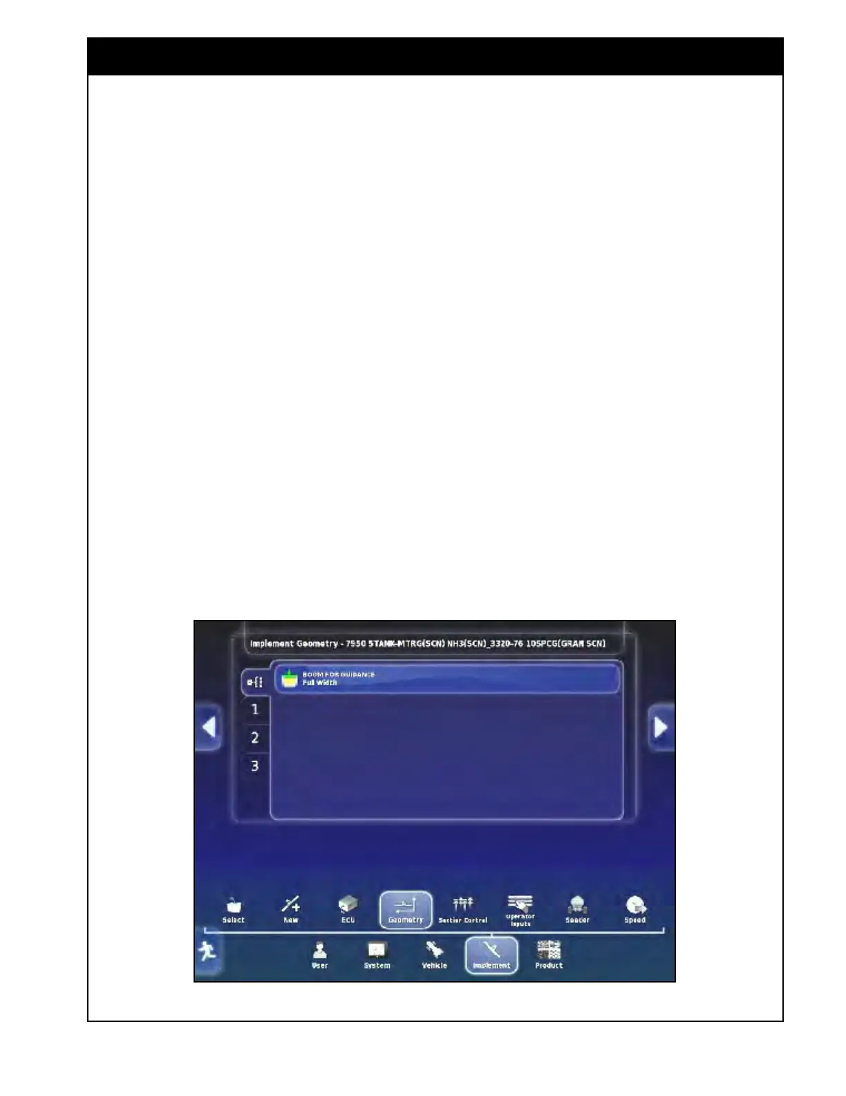
To set implement geometry select Implement/
Geometry. Refer to Figure 6.42
1. Boom for Guidance - this setting is designed
for
Topcon Auto Steer Control and will let you
select what boom should be used for guidance.
a. For more information refer to the Topcon
Auto Steer operators manual.
i. This setting can be left at the default
Full Width.
6.5 Geometry
Figure 6.42 - Implement Geometry
2. Boom Geometry - there will be a separate
geometry tab for each boom depending on the
configuration of your machine.
Full Width Boom
Seed Boom
Fertilizer Boom
Liquid or NH3 Boom
Drill Control Boom
a. If a "Factory profile" is selected, most of
the dimensions will be preset.
i. Each boom tab should be reviewed
to enter the appropriate geometry.
ii. This will ensure the correct
application rate and coverage (if
a Custom profile is created all the
dimensions will need to be entered).
b. When the dimension to be set is selected,
the name of the dimension will appear in
the title bar.
i. A numerical keypad will appear.
ii. Enter the dimension value and
confirm.