X35 Monitor Air Seeder Setup
6.32
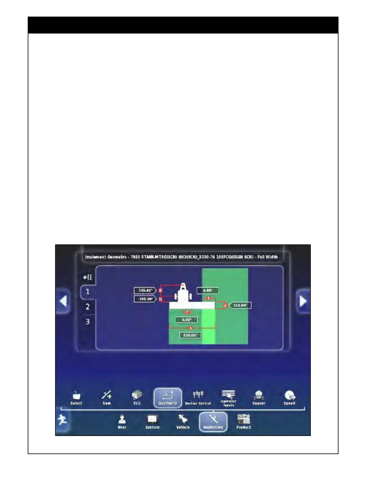
Figure 6.43 - Implement Geometry (Trailing)
Refer to Figure 6.43 & 6.44.
A. Swath Width - sets the working width of the
implement.
i. No multi-section control - enter the
full
width boom working width of the
implement.
ii. Multi-section control
- this is used to view
the dimension. If the dimension is selected
an "Operation Not Permitted" message will
be displayed.
iii. The swath width will be set by the
combination of boom section widths, which
are set in the Implement/Section Control/
Sections setup screen, refer to Section 6.6
- Section
Control.
B. Overlap - indicates the width of the overlap
between two adjacent swathes. It is mostly
used for auto steer and guidance.
i. This value is typically set to 0.
C. Inline Offset - defines the off-centre offset of
the implement relative to the hitch point.
i. Enter a positive number if the implement
is shifted to the right of the hitch point;
ii. Enter a negative number if it is shifted to
the left;
iii. This value is always '0" for a Bourgault
seeding implement.