X35 Monitor Air Seeder Setup
6.33
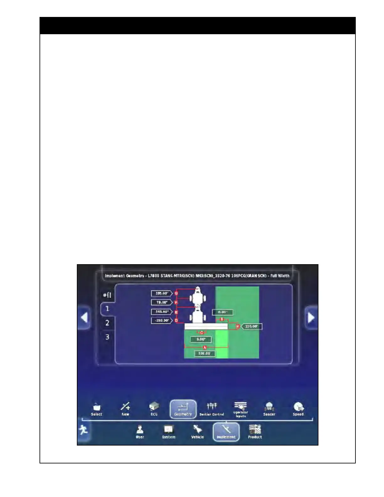
D. Implement Wheels Offset - defines the
distance from pivot point of the drill to front
row of openers. Enter:
i. A negative number for standard machines
as the pivot point is the back tires;
ii. A positive number for a High Flotation
machine as pivot point is the front tires.
E. Implement Offset - is the distance from the
front hitch to pivot point of the drill.
i. For a regular drill, the pivot point is back
tires;
ii.
For
a high flotation drill, the pivot point is
front tires.
Note
The individual boom geometry is set to match
the actual position and depth of the respective
openers for that boom. Factory profiles have the
Fertilizer and NH3/Liquid booms set up assuming
it is using MRB’s. If that is not the case then the
geometry needs to be adjusted for those booms
to match the Seed boom.
F. Trailer Wheels Offset (used for Leading Air
Seeders ONLY) - is the distance from the air
seeder tires to rear hitch pin.
G. Trailer Offset (used for Leading Air Seeders
ONLY) - is the distance from the air seeder
tires to the front hitch pin.
H. Working Length - is the depth of the boom
(distance from the front row of openers to the
back row of openers).
Note
If you are using Auto Section Control (ASC)
to control the product, these dimensions are
extremely important for guidance to perform
accurate coverage.
Figure 6.44 - Implement Geometry (Leading)