X35 ConsoleSystem Components
1.8
1.5.4 SLC2810 Remote Display
(7000 Air Seeders only)
The SLC2810 displays the scale values and can
control the scale link setup.
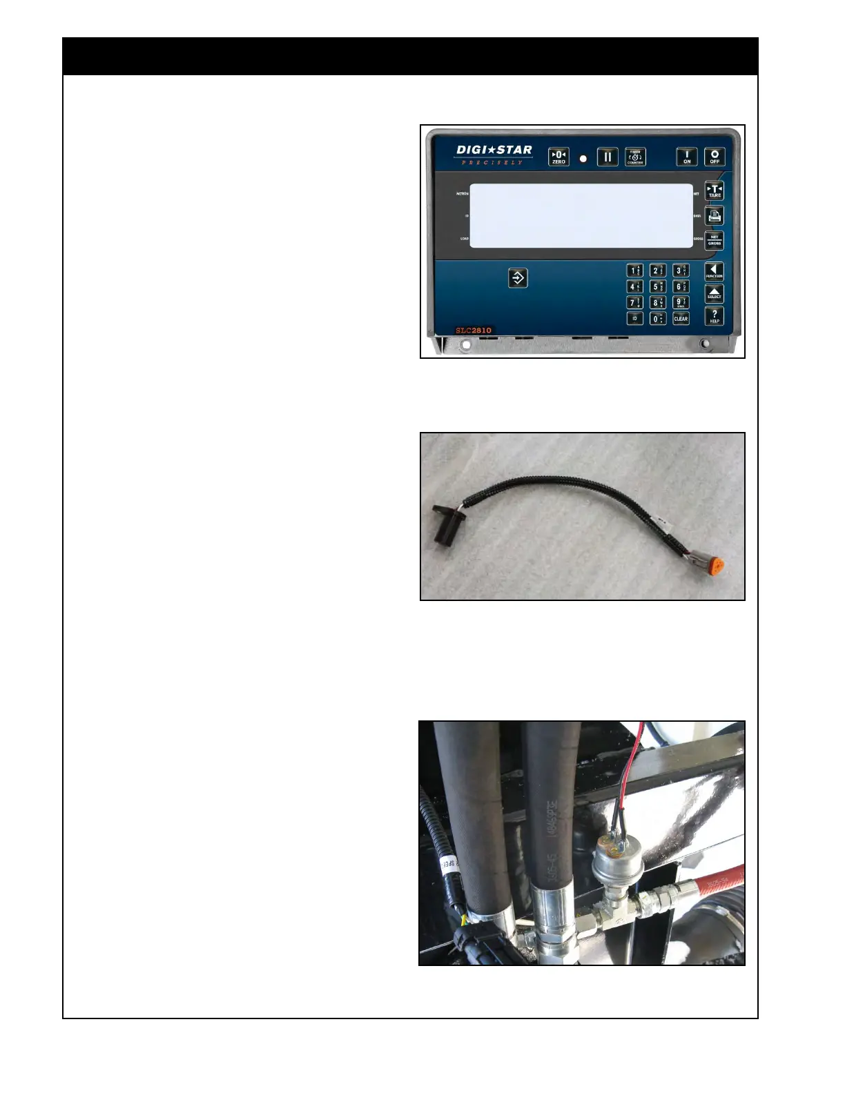
Figure 1.18 - Case Drain Pressure Switch
Casepress_newStyule.jpg
Figure 1.17 - Speed Sensor
SpeedSensor.jpg
1.6 Speed Sensors
There are speed sensors in several locations on the
air seeder. These include fan speed, ground speed,
and metering auger speed. All of these sensors are
proximity style and send a signal to the ECU.
1. The fan speed sensor picks up from a target
bolt on the fan hub (one pulse per revolution).
2. The ground speed sensor is located on the
rear left wheel mount or drive. It picks up a
signal from a sprocket.
3. The metering auger sensors are on the
metering auger housing and pick up the signal
from a sprocket on the metering auger shaft:
a. 32 pulses per revolution for
7000/8000/9000 Series Air Seeders.
b. 16 pulses per revolution for 6000 Series
Air Seeders.
EZ2810_WeighScaleMonitor.jpg
Figure 1.16 - Weigh System Remote Display
1.7 Case Drain Pressure Switch
A pressure switch (Figure 1.18) is installed in the
fan hydraulic motor case drain line. This controls
an alarm that will activate if the case drain
pressure is too high, greater than 65 psi (448 kPa).
Important
High case drain pressure may result in damage to
the hydraulic motor.