X35 Console Overview
2.5
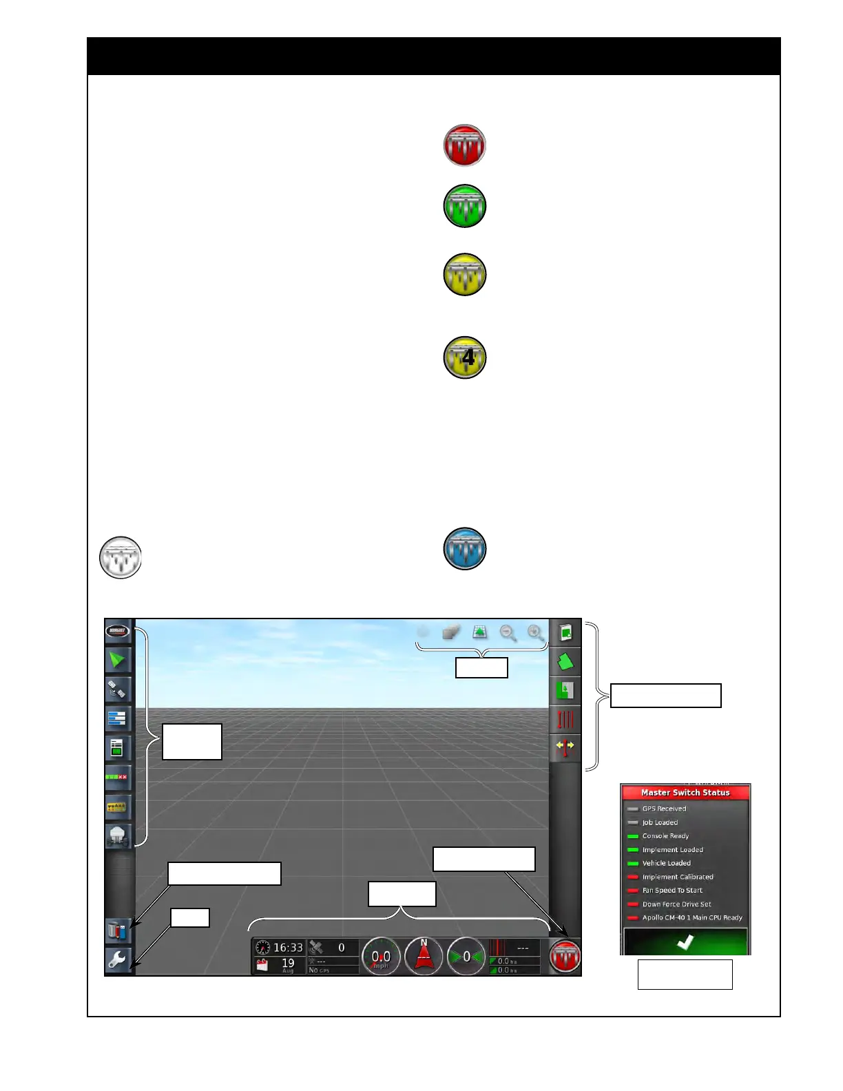
2.3 Understanding the Main Screens
Figure 2.7 - Main Operator's Screen
MainOperScreen.jpg
2.3.1 Operations Screen
The operations screen will allow you to access all
the controls available on the X35 Console. The
functions on the screen are separated into several
main areas, refer to Figure 2.7:
1. Mini-V
iew Menu - displays buttons for
enabled features.
2. Job/Guidance
Menu - provides tools to
control guidance; set auto steering options;
set client, farm, field, boundaries, flag points,
exclusion zones; select or setup specific job
information associated with the chosen field.
3. Map
Menu - provides tools to control what is
displayed on the guidance map.
4. Dash
Board - allows user to choose items that
are preferred to monitor.
5. V
irtual Master Switch - turns the master
switch ON/OFF and displays the state of the
master switch.
When the system is ready to seed, the
Master
Switch icon is White.
Mini-View
Menu
Map Menu
Dash Board
Setup
Virtual Master Switch
Inventory Manager
When the system is not ready, the icon
will be Red. Press the icon to bring up
a Status menu to see what is preventing
seeding.
When
the Master Switch is turned on and
the unit is seeding the icon will be Green.
When
the Master Switch is turned on but
something is stopping the meters from
turning the icon will be Yellow. (e.g. ASC
over coverage, tanks switched off, etc.)
When the Master Switch is turned on
with no speed and there is a Preload Time
entered the icon with flash between Yellow
and White with a number counting down over
it. The product will start and the timer will count
down; allowing you to start seeding from a stop
without missing the beginning area if the Preload
Time is set appropriately to allow product to be at
the ground. Just before the timer hits zero start
moving and the product will continue flowing.
When the Implement Master Switch is
used as a secondary switch and the Master
is on but the implement is lifted the icon
will be Blue. The product will remain off in this
state
until the implement is lowered.
Grey/Red - Not ready
Green - Ready
Job/Guidance Menu