Maintenance
3603−1/A1
RT-flex50-D
Wärtsilä Switzerland Ltd
3/ 3
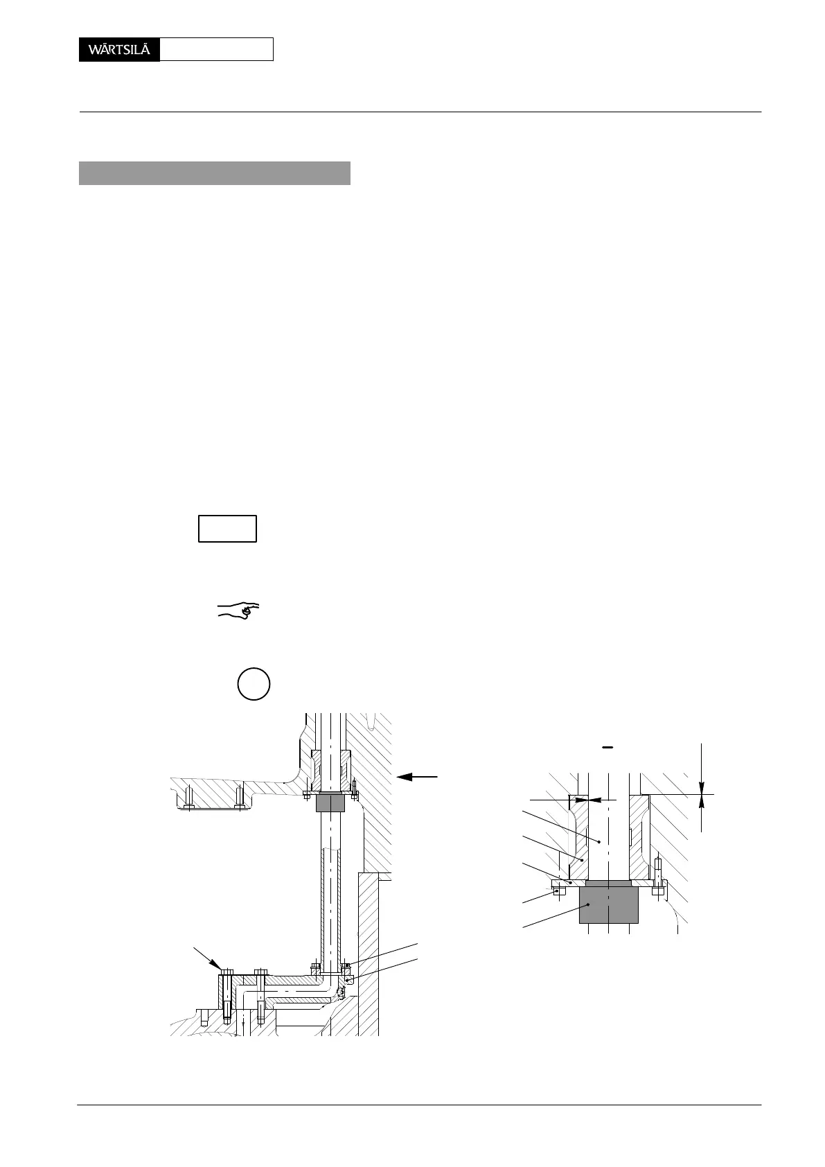
3. Fitting
⇒ Turn the corresponding crank to B.D.C.
⇒ Push ring holder 4 and sleeve 5 over inside pipe 6.
⇒ Fasten lifting tool 94337 to inside pipe and connect it to lifting tackle ’HZ’ as
shown in Fig. ’B’ view I.
⇒ Lift inside pipe, put it onto connection piece 8 and hold it loosely with screws 2
(Fig. ’C’).
⇒ Carefully turn the crank approx. 30_ after T.D.C.
⇒ Push up ring holder with sleeve into the bore of cylinder block 7 and hold them
loosely with screws 3.
⇒ Slightly tighten screws 2 and 3, that inside pipe and ring holder still can be
moved.
⇒ Align ring holder and inside pipe by means of centring piece 94337a till the
clearance ’x’ = 0.30 − 0.39 mm is adjusted.
⇒ Tighten screws 2 and 3.
Check clearance ’x
1
’ = 0.08 − 0.20 mm and recheck clearance ’x’.
⇒ Lock screws 2.
⇒ Install oil inlet pipe 1 (Fig. ’A’).
Remark: Every time if screws 2, 3 or 10 have been loosened, inside pipe 6 must be
aligned and clearances ’x’ as well as ’x
1
’ checked.
F
013.418/05
013.419/05
94337a
I
2
8
6
5
4
3
x
x
1
I
10
Piston Cooling and Crosshead Lubrication: Removal and Fitting of Inside Pipe
2010
CHECK