Chapter 1 System Introduction
OLT2406 User’s Guide
36
The following table describes the OLT slots, cards, and modules.
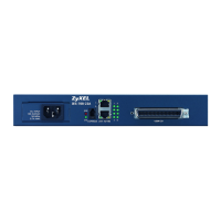
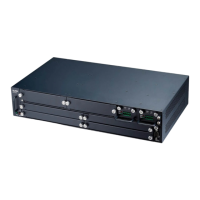
1.4 Management Switching Card
The management switching card connects the OLT to the backbone and manages and monitors the
OLT and the services of the line cards. This card is hot-swappable.
Figure 3 Management Switching Card Front Panel
This table describes the front panel LEDs of the card.
Table 1 Slots and Cards
SLOT SLOT TYPE
MODULE OR
CARD NAME
DESCRIPTION
Fan module OFC2406 Controls and monitors the fans.
1 ~ 2 Management
switching card
OMU2442 The management switching card connects the OLT to the
backbone and manages and monitors the OLT and the services
of the line cards. Install a management switching card in either
slot. Install a second to keep in standby as a backup.
Power module OPA2406 DC power module outputs power to the backplane.
3 ~ 6 Fiber access line
card
OLC2404-22 Maximum 4 GPON cards support up to 1024 PON subscribers.
OLC2504-42 Maximum 4 Gigabit Ethernet cards support up to 16 active fiber
devices such as chassis-based and standalone MDUs.
Alarm module ALM2406 For connecting alarm inputs and outputs.
Table 2 Management Switching Card LED Descriptions
LED COLOR STATUS DESCRIPTION
SFP 1 ~ 2
LINK
Green On A 1 Gbps Ethernet link is up.
Off The Ethernet link is down.
SFP 3 ~ 6
LINK
Green On A 10 Gbps or 1 Gbps Ethernet link is up.
Off The Ethernet link is down.
SFP ACT Green Blinking The slot is transmitting or receiving Ethernet traffic.
Off The connection is idle.
MGMT Amber Blinking The port is transmitting/receiving to/from a 100 Mbps Ethernet network.
On A 100 Mbps Ethernet link is up.
Off The Ethernet link is down.
Green Blinking The port is transmitting/receiving to/from a 10 Mbps Ethernet device.
On A 10 Mbps Ethernet link is up.
Off The Ethernet link is down.
 Loading...