Chapter 1 System Introduction
OLT2406 User’s Guide
41
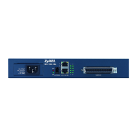
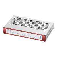
Figure 8 GE Line Card Front Panel
The GE line card supports LC duplex receptacles and transceivers that comply with the IEEE 802.3z. & SFP
MSA standard (SFF-8472). See Section 2.5 on page 49 for how to install transceivers.
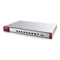
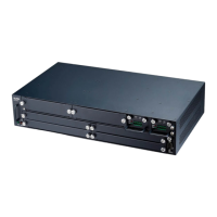
1.7 Power Module
The power module connects to -48 VDC line power.
Figure 9 Power Module Front Panel
This table describes the LEDs on the power module front panel.
See Section 110.1 on page 741 for power module specifications.
Table 9 GE Line Card LED Descriptions
LED COLOR STATUS DESCRIPTION
PWR Green On The line card is powered on.
Off The line card is not powered on or has failed.
ALM Red On A Gigabit Ethernet interface has an alarm.
Off The Gigabit Ethernet interfaces are operating normally.
LNK Green On A 1 Gbps Ethernet link is up.
Off The Ethernet link is down.
ACT Green Blinking The Ethernet link is sending or receiving traffic.
Off The Ethernet link is not sending or receiving traffic.
PWR
ALM
3
142
SFP1 SFP2 SFP3 SFP4
OOLC2504-42
LINK
ACT
Table 10 Power Module LED Descriptions
LED COLOR STATUS DESCRIPTION
ALM Red On The power module is not working normally.
Off The power module is working normally.
PWR Green On The power module is powered on.
Off The power module is turned off or has failed.
 Loading...