Chapter 1 System Introduction
OLT2406 User’s Guide
37
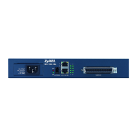
1.4.1 Management Switching Card Ports
Note: Install the management switching card before you make the hardware connections.
See Section 2.4 on page 45.
1.4.2 Uplink and Subtending Slots
The management switching card has 4 slots compliant with IEEE 802.3ae for Enhanced Small Form-factor
Pluggable (SFP+) transceivers (10 Gigabit Ethernet or 1 Gigabit Ethernet) for backbone or subtending
connections. It also has 2 SFP slots for backbone or subtending connections. Transceivers are not
included. See Section 1.4.4 on page 39 for specifications of the supported optical transceivers. See
Section 2.5 on page 49 for how to install transceivers.
To avoid possible eye injury, do not look into an operating fiber-optic
transceiver’s connectors.
You can change transceivers while the OLT is operating. Use different transceivers to connect to
backbone Ethernet switches with different types of fiber-optic connectors.
SYS/ALM Green Blinking The system is initializing.
On The management switching card is on and functioning properly.
Off The management switching card is not receiving power, is not ready or has
malfunctioned.
Red On An alarm has been detected on the OLT. Examples of an alarm on the OLT are
when the OLT’s voltage or temperature is outside of the normal range.
Off The OLT has not detected an alarm on itself.
PWR Green On The management switching card is powered on.
Off The management switching card is not powered on or has failed.
Table 2 Management Switching Card LED Descriptions
LED COLOR STATUS DESCRIPTION
Table 3 Management Switching Card Port Descriptions
LABEL DESCRIPTION
SFP1 ~ SFP2 Use these 1 GbE SFP slots for uplink and subtending connections.
SFP3 ~ SFP6 Use these 10G/1GbE SFP+ slots for uplink and subtending connections.
MGMT Connect this RJ-45 Ethernet port to an Ethernet network for out-of-band management (A
separate channel for management that is not part of the channels that are usually used for data
transfer).
CONSOLE Connect this RJ-45 female connector to a computer for local management.
ACO Press the Alarm Cut Off (ACO) button to cancel an alarm. This stops the sending of the alarm
signal current. This is useful in stopping an alarm if you have the alarm output connector pins
connected to a visible or audible alarm. The alarm entry remains in the system.

 Loading...