Chapter 1 System Introduction
OLT2406 User’s Guide
42
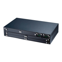
1.8 Fan Module
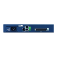
The following figure shows the OLT chassis fan module’s front panel.
Figure 10 Fan Module
This table describes the LEDs on the front panel of fan module .
The fan module monitors to detect whether the fans are operating in the normal state and relays the
information to the OLT’s management switching card.
The fan module is hot-swappable. Replace the entire fan module if cleaning the fan filter does not solve
the problem. Return any malfunctioning fan modules to the manufacturer. Removing the fan module or
fan RPMs, temperature, or voltage values outside of the accepted threshold triggers a critical alarm and
turns on the management switching card’s Alarm LED.
The OLT automatically adjusts the rotation speed of the fans based on the detected temperature. You
can also manually set the high and low fan speed limits for raising an alarm on a specific fan. The
following table covers how the OLT automatically adjusts the rotation speed of the fans based on the
detected temperature. See Section 52.7 on page 402 for how to display the fan speed. See Section
110.1 on page 741 for fan module specifications.
Table 11 Fan Module LED Descriptions
LED COLOR STATUS DESCRIPTION
PWR Green On The fan module is powered on.
Off The fan module is powered off or has failed.
ALM Red On The fan module is not working normally.
Off The fan module is working normally.
 Loading...