2.6 Checking Instrument Status
2-19
2
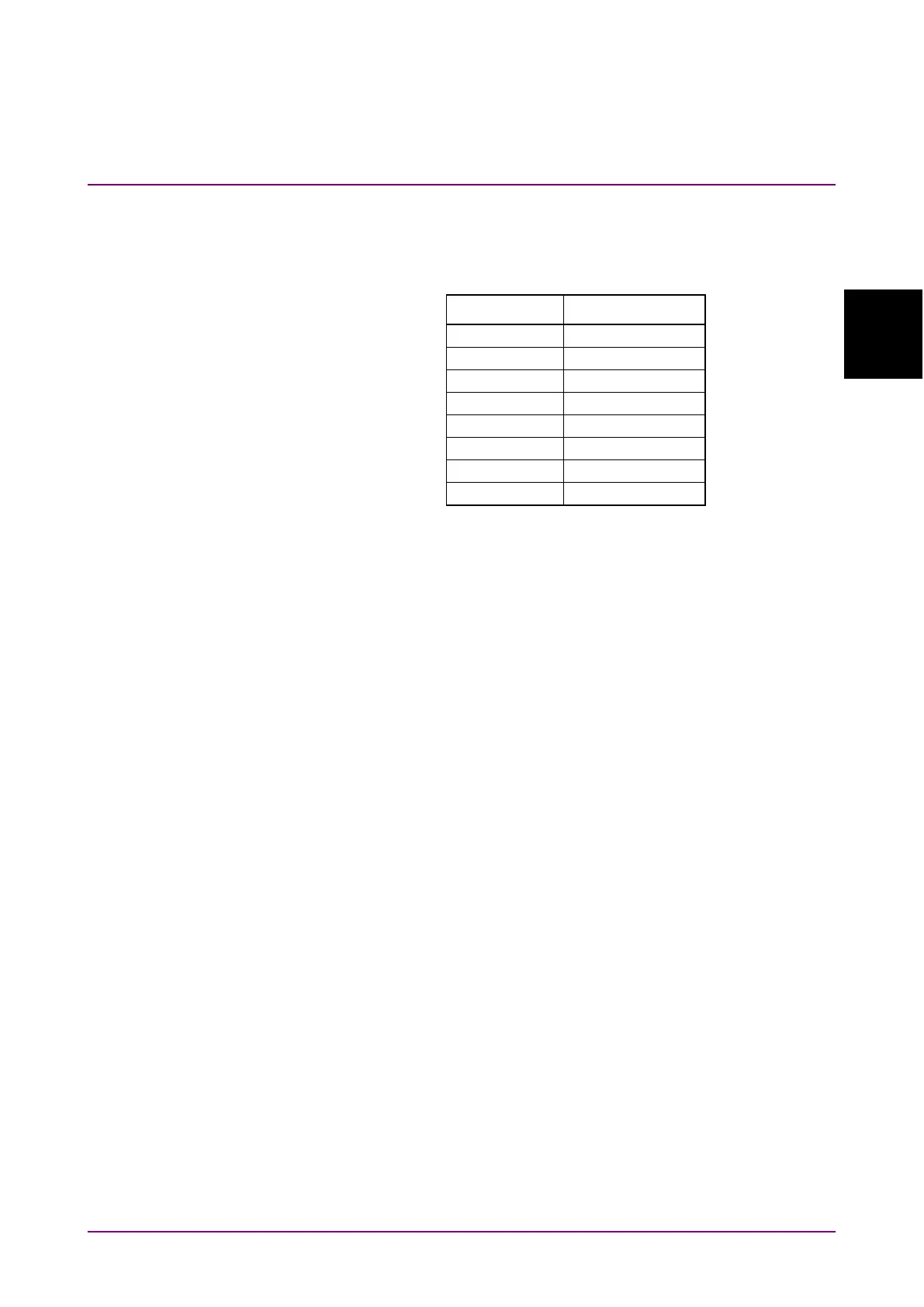
Each register uses 8-bit data. The register output values are the decimal
totals for each bit shown in Figure 2.6.1-1.
Table 2.6.1-1 Register Bit Decimal Conversion Values
Bit Decimal value
The service request enable register has a corresponding status byte
register. The logical product per bit of these two registers is obtained and
the logical sum of this result is output to the MSS (Master Summary
Status) bit. When the MSS bit is 1, the data report to the PC controller is
displayed on the MS9740A screen; when the MSS bit changes from 0 to 1,
an interrupt is generated from MS9740A to the PC controller. This
interrupt is called the service request.
Each standard event register (standard, error, end) has a corresponding
enable register. The logical product per bit of the event and enable
registers is obtained and the logical sum of this result is output to bit 5, 3
and 2 of the status byte register.