4.9 Motor Assembly
Chapter 4: Removal, Replacement, and Adjustment Procedures
Page 4 - 26 Isolette® Infant Incubator (Model C2000) Service Manual
10.Stand at the same end of the shell assembly (B) as the controller
assembly (A), and perform the following:
a. Using the mattress tilt knob (F) and the rear hood hinge (G), lift
the shell assembly (B) enough to access the corrugated hose (H)
at the check valve assembly (I).
b. Using pliers, disconnect and remove the corrugated hose (H)
from the shell assembly (B) and the shell bottom (D).
c. Carefully remove the shell assembly (B) from the shell bottom
(D), and place it upside down on a flat, padded surface.
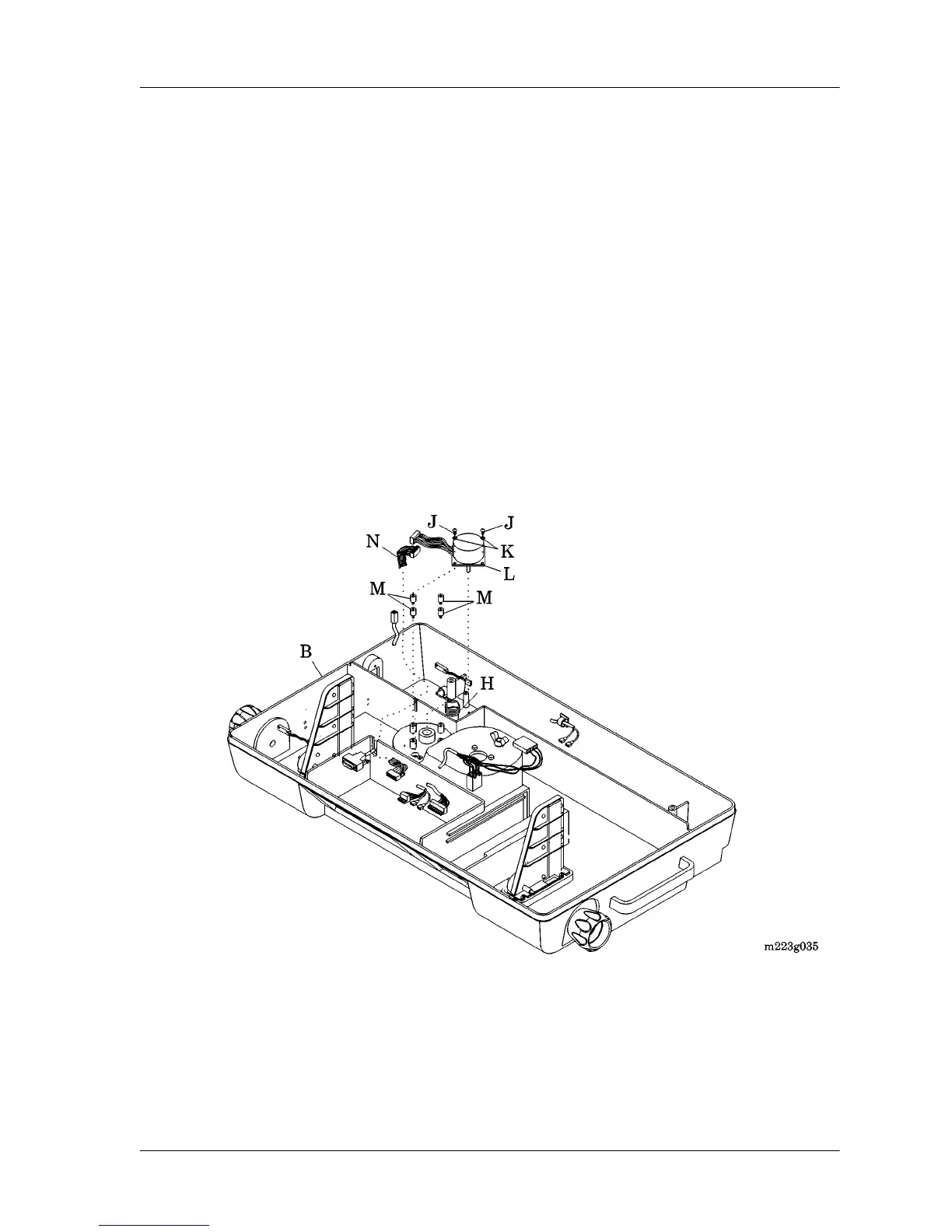
11. Remove the four screws (J) and the four lockwashers (K) that
secure the motor assembly (L) to the shell assembly (B) (see figure
4-10 on page 4-26). Retain the four screws (J) and the four
lockwashers (K).
Figure 4-10. Motor Assembly
12.Remove the motor assembly (L) and the four vibration isolators (M)
from the shell assembly (B). Retain the four vibration isolators (M).
13.Disconnect the motor assembly (L) from the incubator motor-to-
controller cable assembly (N).