Home
GE
Medical Equipment
Vivid S6 N
Page 164 (3-6-2-5-1 Regional Options)
GE Vivid S6 N - 3-6-2-5-1 Regional Options
834 pages
Manual
To Next Page
To Next Page
To Previous Page
To Previous Page
Loading...
GE
P
ART
N
UMBER
FN091065, R
EVISION
2
VS5
N
AND
VS6
N
S
ERVICE
M
ANUAL
3-88
Section 3-4 - Pr
eparing for Installation
PRELIMINARY
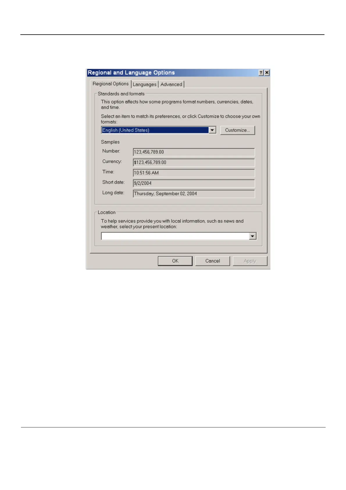
3-6-2-5-1
Region
al Options
•
Select appropriate Fo
rmat and Location, then click
Apply.
Figure 3-100 Regional Options
163
165
Table of Contents
Main Page
Vivid™ S5 N and Vivid™ S6 N
1
Important Precautions
3
LEGAL NOTES
16
Revision History
17
List of Effected Pages (LOEP)
17
Introduction
33
Section 1-1 Overview
33
1-1-1 Purpose of Chapter 1
33
1-1-2 Purpose of Service Manual
34
1-1-3 Typical Users of the Service Manual (This Manual)
34
1-1-4 Vivid™ S5 N and Vivid™ S6 N Models Covered in this Manual
35
1-1-5 Product Description
36
1-1-5-1 Overview of the Vivid™ S5 N and Vivid™ S6 N Ultrasound system
36
1-1-6 Purpose of Operator Manual(s)
36
Section 1-2 Important Conventions
37
1-2-1 Conventions Used in this Manual
37
1-2-1-1 Model Designations
37
1-2-1-2 Icons
37
1-2-1-3 Safety Precaution Messages
37
1-2-1-4 Standard Hazard Icons
38
Section 1-3 Safety Considerations
39
1-3-1 Introduction
39
1-3-2 Human Safety
39
1-3-3 Mechanical Safety
41
1-3-4 Electrical Safety
43
1-3-4-1 Probes
43
1-3-4-2 Peripherals
44
Safety and Environmental Guidelines
44
1-3-5 Vivid S5 N / Vivid S6 N Battery Safety
46
1-3-6 Patient Data Safety
47
1-3-7 Dangerous Procedure Warnings
48
Section 1-4 Lockout/Tagout (LOTO) requirements
49
Section 1-5 Product Labels and Icons
50
1-5-1 Product Labels (Label, General info)
50
1-5-2 Label Descriptions and Locations
52
1-5-3 Vivid™ S5 N and Vivid™ S6 N External Labels
55
1-5-3-1 Product Labels
55
1-5-3-2 GND Label
55
Section 1-6 Returning/Shipping Probes and Repair Parts
56
Section 1-7 EMC, EMI, and ESD
57
1-7-1 Electromagnetic Compatibility (EMC)
57
1-7-2 CE Compliance
57
1-7-3 Electrostatic Discharge (ESD) Prevention
57
1-7-4 General Caution
57
Section 1-8 Customer Assistance
59
1-8-1 Contact Information
59
1-8-2 System manufacturer
61
Site Preparations
63
Section 2-1 Overview
63
2-1-1 Purpose of Chapter 2
63
Section 2-2 Console Requirements
64
2-2-1 Unit Environmental Requirements
64
2-2-2 Cooling Requirements
64
2-2-3 Lighting Requirements
64
2-2-4 Time and Manpower Requirements
65
2-2-5 Electrical Requirements
66
2-2-5-1 Vivid™ S5 N and Vivid™ S6 N Power Requirements
66
2-2-5-2 Inrush Current
66
2-2-5-3 Site Power Outlets
66
2-2-5-4 Mains Power Plug
66
2-2-5-5 Power Stability Requirements
67
2-2-6 EMI Limitations
67
2-2-7 Probe Environmental Requirements
68
Section 2-3 Facility Needs
69
2-3-1 Purchaser Responsibilities
69
2-3-2 Mandatory Site Requirements
70
2-3-3 Site Recommendations
70
2-3-3-1 Recommended Ultrasound Room Layout
71
2-3-4 Networking Pre-Installation Requirements
72
2-3-4-1 Stand-alone Unit (without Network Connection)
72
2-3-4-2 Unit Connected to Hospital’s Network
72
2-3-4-3 Purpose of the DICOM Network Function
72
2-3-4-4 DICOM Option Pre-Installation Requirements
72
Section 2-4 Connectivity Installation Worksheet
73
System Setup
77
Section 3-1 Overview
77
3-1-1 Purpose of Chapter 3
77
Section 3-2 Installation Reminders
78
3-2-1 Average Installation Time
78
3-2-2 Installation Warnings
78
3-2-2-1 System Acclimation Time
78
3-2-3 Safety Reminders
79
Section 3-3 Receiving and Unpacking the Equipment
80
3-3-1 Unpacking the Cardboard Shipping Carton
84
3-3-1-1 Unpacking the Vivid S5 N or Vivid S6 N with Peripherals
84
3-3-1-2 Unpacking the Vivid S5 N or Vivid S6 N
85
3-3-2 Verifying the Shipping Carton Contents
89
3-3-3 Physical Inspection
89
3-3-3-1 System Voltage Settings
89
3-3-4 EMI Protection
89
Section 3-4 Preparing for Installation
90
3-4-1 Confirming Customer Order
90
3-4-1-1 Probes
90
3-4-2 Language Change
90
Language Selection
90
Verifying the Language Change
93
3-4-3 Component Inspection
94
3-4-3-1 Damage Inspection Checklist
94
3-4-3-2 Front View of the Vivid S5 N or Vivid S6 N Ultrasound Unit
96
3-4-3-3 Rear View of the Vivid S5 N or Vivid S6 N Ultrasound Unit
98
3-4-3-4 Rear Panel of the Vivid S5 N or Vivid S6 N Ultrasound Unit
99
3-4-4 System Voltage Confirmation
100
3-4-4-1 System Voltage Settings
100
3-4-5 Ensuring Protection from EMI
101
Section 3-5 Completing the Hardware Installation
102
3-5-1 Connecting Printers
103
3-5-1-1 Printer Connection and Configuration - Overview
103
3-5-1-1-1 Printer Categories and Outline of Procedure Instructions
103
3-5-1-1-2 Configuring Printing Buttons P1 and P2
103
P1 and P2 Hot Key Configuration via Vivid S5 N/ Vivid S6 N Connectivity Settings
104
P1 Button Configuration via the Windows Control Panel
105
3-5-1-1-3 Setting Printing Orientation (Portrait or Landscape) and Paper Size
109
3-5-1-2 HP470 /HP100 Color Printer
111
3-5-1-3 HP 5400K DeskJet Color Printer
112
3-5-1-3-1 Configuring the HP 5400K DeskJet Color Printer for Connection via USB Port
113
3-5-1-3-2 Setting the HP 5400K DeskJet Color Printer as the Default Report Printer
116
3-5-1-4 HP OfficeJet Pro 8000 Color Printer
118
3-5-1-4-1 Connecting the HP OfficeJet Pro 8000 Directly to the Vivid S5 N/ Vivid S6 N System
118
3-5-1-4-2 Connecting the HP OfficeJet Pro 8000 to a Local Area Network (LAN)
121
Preparation
121
Procedure
122
3-5-1-5 HP LaserJet CP2025/M451 Color Printer
128
3-5-1-5-1 Peer-to-Peer Configuration
129
Defining the IP address of the Vivid S5 N/ Vivid S6 N System
129
Defining the Printer IP Address
131
Driver Installation
133
Defining the Paper Size
135
3-5-1-5-2 Installing the HP LaserJet CP2025 Color Printer on a Network
135
3-5-1-6 Sony UP-D897 B/W Video Printer
135
3-5-1-6-1 Configuring the Sony UP-D897 B/W Video Printer
137
3-5-1-7 Sony UP-D25MD Color Video Printer
140
3-5-1-7-1 Connecting the Color Video Printer
141
3-5-2 Connecting Peripherals
142
3-5-2-1 Wireless Network Adaptor
142
3-5-2-2 MOD Drive
143
3-5-2-3 External USB Hard Disk
143
3-5-2-4 USB Memory Stick
144
3-5-2-5 Footswitch
144
3-5-3 Connecting Probes
147
3-5-3-1 Available Probes
148
3-5-4 Connecting the ECG
149
3-5-5 Connecting the Unit to a Power Source
151
3-5-5-1 Voltage Level Checks
151
3-5-5-2 Connecting the Ultrasound Unit to the Electrical Outlet
151
3-5-5-3 Disconnecting the Ultrasound Unit from the Electrical Outlet
154
3-5-6 Switching the System ON/OFF
155
3-5-6-1 Switching the System ON
155
3-5-6-2 Switching the System OFF
155
Section 3-6 Configuration
156
3-6-1 Vivid S5 N and Vivid S6 N Configuration
156
3-6-1-1 Enter Location
156
3-6-1-2 Date and Time Adjustments
157
3-6-1-3 Language Selection
158
3-6-1-4 Units of Measure
160
3-6-2 Service Screen Set-up
161
3-6-2-1 Overview
161
3-6-2-2 Open Service Screen
161
3-6-2-3 Adjust Keyboard Backlight Intensity
162
3-6-2-4 LCD Display Adjustment and Calibration
162
3-6-2-5 Keyboard Setup
163
3-6-2-5-1 Regional Options
164
3-6-2-5-2 Languages
165
3-6-2-5-3 Advanced
166
3-6-2-6 Add Printer
167
3-6-3 Configuring Peripherals
168
3-6-3-1 Approved Peripherals
168
3-6-3-2 Network Peripherals (Optional)
168
3-6-3-3 Virtual Printing (Optional)
169
3-6-4 Software Options Configuration
171
3-6-4-1 Software Option Installation
171
3-6-4-2 On-site Configuration
171
Section 3-7 Connectivity Setup
172
3-7-1 Connectivity Introduction
172
3-7-1-1 The Dataflow Concept
172
3-7-1-2 Dataflow Naming Convention
176
3-7-1-3 Dataflow Examples
177
3-7-1-4 Stand-alone Vivid S5 N or Vivid S6 N
177
3-7-1-5 “Sneaker Net” Environment
177
3-7-1-6 Direct Connection from Vivid S5 N or Vivid S6 N to an EchoPAC PC Workstation
178
3-7-1-7 Vivid S5 N or Vivid S6 N and a DICOM Server in a Network
178
3-7-2 Physical Connection
179
3-7-2-1 Ethernet Switch Connections
179
3-7-2-2 Local Network Connection to EchoPAC PC Workstation
179
3-7-2-3 Hospital Network Connection to EchoPAC PC Workstation
180
3-7-2-4 Wireless Network Configuration
181
3-7-2-4-1 Configuring the Wireless Network Adaptor
181
3-7-2-5 Stand-alone Vivid S5 N or Vivid S6 N
184
3-7-2-6 “Sneaker Net” Environment
184
3-7-2-7 Connection from Vivid S5 N or Vivid S6 N to an EchoPAC PC Workstation
184
Direct Cable Connection from Vivid S5 N or Vivid S6 N to an EchoPAC PC Workstation via a Crossover Cable
184
Connection via a Peer-to-Peer Network
184
Connection via Hospital Network
184
3-7-2-8 Connection between a Vivid S5 N or Vivid S6 N and a DICOM Server on a Network
184
3-7-3 Connectivity Configuration
185
3-7-3-1 Introduction
185
3-7-3-2 Select TCP/IP Set-up Screen
185
3-7-3-3 Set the Scanner’s Network Information
186
3-7-3-4 Set the Remote Archive’s Network Information
186
3-7-3-5 Vivid S5 N/ Vivid S6 N Remote Path Configuration
186
3-7-3-6 Configuring the Vivid S5 N / Vivid S6 N Remote Path
187
3-7-3-6-1 Configuring the Repository Remote Path
188
3-7-3-7 Configuring the Vivid S5 N or Vivid S6 N and Network PC for a Peer-to-Peer Connection
188
3-7-3-8 Configuring the Vivid S5 N or Vivid S6 N and Network PC for a LAN Connection
191
3-7-4 Set Up Connection to a DICOM Server in a Network
196
3-7-4-1 Overview
196
3-7-4-2 DICOM Server IP Address Setting on the Scanner
196
3-7-4-3 Verify the Connection to a Device
200
3-7-5 Setup Connection to HL7 Server in a Network
201
3-7-5-1 Introduction
201
3-7-5-2 Preparations
201
3-7-5-3 Configuration of Modality Worklist Services
201
Identify Dataflow to be Used
201
Configure the DICOM Worklist Service
201
Configure the Search Criterias
202
Configure Search Criteria: Constrain Query by AE Title
202
Configure Search Criteria: Constrain Query by MRN
202
Assign DICOM Worklist name to Dataflow
202
Test Connectivity with the Vivid HL7 Gateway
202
Troubleshoot Connectivity with the Gateway
203
Configure the Export to HL7 Path
203
Test Connectivity with the Vivid HL7 Gateway
203
Troubleshoot Connectivity with the Vivid HL7 Gateway
204
3-7-6 Query/Retrieve (Q/R) Setup
205
3-7-6-1 Overview
205
3-7-6-2 Query/Retrieve Setup on the Vivid S5 N or Vivid S6 N
205
Change Search Criterias
207
3-7-6-3 Query/Retrieve Verification
209
Follow the Steps Below to do a First Test (Ping) of the Connection
209
Follow the Steps Below to Test the DICOM Query/Retrieve Workflow
209
3-7-7 MPEGVue Export Configuration
212
3-7-7-1 Introduction
212
3-7-7-2 Preparations
212
3-7-7-3 Configuring the Vivid S5 N or Vivid S6 N for MPEGVue Export
212
3-7-7-4 Exporting to MPEGVue
215
3-7-8 eVue Dataflow Configuration
217
3-7-8-1 Introduction
217
3-7-8-2 Preparations
217
3-7-8-3 Configuring the Vivid S5 N or Vivid S6 N for eVue Dataflow
217
3-7-8-4 Using eVue
219
3-7-9 Using MPEGVue/eVue on a Remote PC
221
3-7-9-1 Installing MPEGVue on a Remote PC
221
3-7-9-1-1 Manually Setting the Network PC for eVue Import
222
3-7-9-1-2 Manually Stopping the Firewall on the Network PC
229
Stopping the Windows Firewall
229
Stopping an External Service Firewall
231
Stopping the Firewall on Windows XP Service Pack 2
233
3-7-9-2 Un-installing MPEGVue on a Remote PC
234
3-7-9-3 Using MPEGVue Viewer on a Remote PC
237
3-7-9-3-1 Reading an MPEGVue Exam
237
3-7-9-3-2 MPEGVue Patient List
237
3-7-9-3-3 Selecting an Image
238
3-7-9-3-4 Stopping & Running the Cine-Loop
239
3-7-9-3-5 Selecting a Different Patient
239
3-7-9-3-6 Exporting Images or Loops from MPEGvue
239
3-7-9-3-7 Performing Measurements on MPEGVue Images
239
3-7-9-3-8 Saved Worksheets
240
3-7-9-3-9 Reports (.CHM files)
240
3-7-9-3-10 Using MPEGVue over E-mail
240
Sending a Full Examination by E-mail
240
Sending an image by E-mail
242
Sending the MPEGVue Player Software by E-mail
244
First Time Receipt of MPEGVue Player Software and Images by E-mail
245
3-7-9-3-11 Managing and Viewing Exams Received
245
3-7-9-3-12 Get New Exams by E-mail
247
Receiving and Viewing a Partial Examination
250
View previous exams from E-mail
250
Activate e-Vue
251
Using Patient Manager
251
3-7-9-3-13 Using MPEGVue Player
258
Section 3-8 Storing and Transporting the Unit
262
3-8-1 Safety Precautions for Moving the Vivid S5 N or Vivid S6 N Unit
262
3-8-2 Cardboard Shipping Carton and Packaging Materials
267
Section 3-9 Completing the Installation Paperwork
268
3-9-1 Installation Acceptance Test Criteria
268
3-9-2 System Installation Details
268
3-9-3 Product Locator Installation
268
3-9-4 User Manual(s)
269
Functional Checks
271
Section 4-1 Overview
271
4-1-1 Purpose of Chapter 4
271
4-1-2 Specific Equipment Required
271
Section 4-2 General Procedures
272
4-2-1 Overview
272
4-2-2 Power ON/Boot-up
272
4-2-2-1 Connecting Mains Power to the Vivid S5 N or Vivid S6 N Ultrasound Unit
272
Follow These Steps to Connect Mains Power to the Unit
273
4-2-2-2 Turning the System ON
275
4-2-3 Power Shut Down
277
4-2-3-1 Standby Mode
278
Follow the steps below to select Standby Mode
278
Follow steps below if you need to disconnect power cable when unit is in standby mode
278
4-2-3-2 Complete Power Down
279
Follow this procedure to perform a complete system power-down
279
4-2-4 Log On to the System as ADM
280
4-2-5 Using Removable Media
282
4-2-5-1 Introduction
282
4-2-5-2 Install MO Disk in MO Drive
282
4-2-5-3 Eject and Remove MO Disk from MO Drive
282
4-2-5-4 Install CD-R Disk in CD Drive
283
4-2-5-5 Eject and Remove CD-R Disk from CD Drive
283
4-2-6 Labeling Removable Media
284
4-2-7 Formatting Removable Media
284
4-2-8 DICOM Repair of Removable Media
285
4-2-9 Archiving and Restoring System Configuration
285
4-2-9-1 Backing Up System Configuration to Removable Media
286
4-2-9-2 Restoring System Configuration from an MO Disk
287
Section 4-3 Functional Checks
288
4-3-1 Basic Controls
288
4-3-1-1 Alphanumeric Keyboard Test
288
4-3-1-2 Extended Keyboard and Trackball Test
288
4-3-1-3 System SN Test
291
4-3-1-4 Speakers Tests
291
4-3-1-5 Light Detector Test for Vivid S6 N only
292
4-3-1-6 Monitor Test
292
4-3-1-7 ECG Test
293
4-3-1-8 Front End Tests
295
4-3-1-9 Visual Test
302
4-3-2 Peripherals
303
4-3-2-1 B/W and Color Printer Test
303
4-3-2-2 Color Printer Test
303
4-3-2-3 External USB Hard Disk Test
304
4-3-3 Mechanical Functional Tests
305
4-3-3-1 Arm Movement Test
305
4-3-3-2 Operator Panel Movement Test
305
4-3-3-3 Monitor Movement Test
306
4-3-3-4 Front Wheel Function Test
306
4-3-3-5 Rear Wheel Function Test
306
4-3-4 Back End Processor Tests
307
4-3-4-1 USB Test
307
4-3-4-2 Standby Test
307
Section 4-4 Image Testing
308
4-4-1 2D Mode (B Mode) Checks
308
4-4-1-1 Introduction
308
4-4-1-2 Preparations
308
4-4-1-3 Adjust the 2D Mode Controls
309
4-4-2 M Mode Checks
309
4-4-2-1 Preparations
310
4-4-2-2 Adjust the M Mode Controls
310
4-4-3 Color Mode Checks
310
4-4-3-1 Introduction
310
4-4-3-2 Preparations
310
4-4-3-3 Select Color 2D Mode
310
4-4-3-4 Adjust the Color 2D Mode Controls
310
4-4-3-5 Select Color M Mode
311
4-4-3-6 Adjust the Color M Mode Controls
311
4-4-4 PW/CW Doppler Mode Checks
312
4-4-4-1 Introduction
312
4-4-4-2 Preparations
312
4-4-4-3 Adjust the PW/CW Doppler Mode Controls
312
4-4-5 Tissue Velocity Imaging (TVI) Checks
313
4-4-5-1 Introduction
313
4-4-5-2 Preparations
313
4-4-5-3 Adjust the TVI Controls
313
4-4-6 Probe/Connectors Check
314
Section 4-5 System Turnover Checklist
315
4-5-1 Software Configuration Checks
315
Section 4-6 Site Log
316
Components and Function (Theory)
319
Section 5-1 Overview
319
5-1-1 Purpose of Chapter 5
319
Section 5-2 General Information
319
5-2-1 Introduction
320
5-2-2 Signal Flow
321
5-2-2-1 System Configuration and Software
321
5-2-2-2 Operator Panel
321
5-2-2-3 Electronics
321
5-2-3 Vivid™ S5 N and Vivid™ S6 N Systems - Block Diagram
322
Section 5-3 Front End Unit
323
5-3-1 General Information
323
5-3-2 Front End Unit - Location in the System
326
5-3-3 RFI_AM Board
328
5-3-3-1 Tasks Performed by the RFI_AM Board
328
5-3-3-2 Watchdog and Power ON Reset
328
5-3-3-3 Boot-up of DSP and Firmware
328
5-3-3-4 FPGA Download
329
5-3-3-5 PCI Connection
329
5-3-3-6 RFI_AM Board Connectors
330
5-3-3-7 Probe Management
331
5-3-3-7-1 Mechanism
331
5-3-4 TR32 Boards (Transmitter/Receiver)
332
5-3-4-1 General Description
332
5-3-5 Probe Select Board (PSB)
335
5-3-6 Probe Interface Board (PIB)
337
Section 5-4 Back End Processor
340
5-4-1 Introduction
340
5-4-2 ETX SBC Central Processing Unit (CPU)
342
5-4-3 ETX Base Board
343
5-4-3-1 Overview of ETX Base Board Functions
343
5-4-3-2 VGA Interface
344
5-4-3-3 CardBus Interface
344
5-4-4 Hard Disk
344
5-4-5 Fan Control
345
5-4-6 Temperature Control
345
5-4-7 RTC Battery
345
5-4-8 Back End Processor - Location of Components
346
5-4-8-1 BEP Connectors
347
Section 5-5 Internal and External Input/Output (I/O)
349
5-5-1 DIB - Interconnections
352
Section 5-6 Power Supply System
356
5-6-1 Electrical Power
356
5-6-2 Introduction
356
5-6-3 AC Distribution Panel
357
5-6-4 Power Supply Unit Components
360
5-6-4-1 Critical Temperature Sensor
360
5-6-5 DC Source Selector
360
5-6-6 Rechargeable Battery Pack Assy (GPA)
361
Section 5-7 Top Console with Monitor and Operator Panel
363
5-7-1 Keyboard and Operator Panel
363
5-7-2 Keyboard and Operator Panel Components
364
5-7-2-1 Power ON/OFF Button
364
5-7-2-2 Alphanumeric Keyboard
364
5-7-2-3 TGC Sliders
364
5-7-2-4 Gain Rotaries
365
5-7-2-5 Extended Keyboard
365
5-7-2-6 Trackball
365
5-7-2-6-1 Trackball Buttons
365
5-7-2-7 Key and Backlight Illumination
365
5-7-2-8 USB Hub
366
5-7-2-9 Power Interface
366
5-7-2-10 Keyboard ID
366
5-7-2-11 Keyboard Connectors
366
5-7-2-12 Monitor Connectors
367
5-7-2-13 Display Unit
367
Section 5-8 ECG Module
368
5-8-1 Overview
368
5-8-2 ECG Patient I/O Module Specifications
369
5-8-2-1 Power Consumption
369
5-8-2-2 Sample Rate
369
5-8-2-3 Bandwidth
369
5-8-3 Isolation
369
Section 5-9 Peripherals
370
5-9-1 Introduction
370
5-9-1-1 Printers
370
5-9-1-1-1 Black & White Digital Printer
370
5-9-1-1-2 Color Digital Printer
370
5-9-1-1-3 Color InkJet Printer
370
5-9-1-2 DVD/CD Reader and CD Writer (DVD/CDR-W)
370
5-9-1-3 Magneto-Optical Drive (MOD)
370
5-9-1-4 Wireless Network Adapter
371
Section 5-10 Cooling System
372
5-10-1 General Information
372
Section 5-11 Common Service Platform
373
5-11-1 Introduction
373
5-11-2 Global Service User Interface (GSUI)
373
5-11-2-1 Internationalization
373
5-11-2-2 Service Login
373
5-11-2-3 Access / Security
373
Service Adjustments
375
Section 6-1 Overview
375
6-1-1 Purpose of Chapter 6
375
6-1-2 LCD Display Adjustments and Calibration
375
6-1-2-1 Contrast Adjustment Procedure
376
6-1-2-2 Brightness Adjustment Procedure
377
6-1-2-3 Testing Your Contrast and Brightness Settings
377
6-1-2-4 Blue Tint Adjustment Procedure
378
6-1-2-5 Blue Tint “2” Adjustment Procedure
379
6-1-2-5-1 Adjusting the Blue Tint
380
6-1-2-5-2 Turning Off the Blue Tint “2” Option
381
6-1-2-6 Autosensor Adjustment Procedure for Vivid S6 N only
381
6-1-2-7 Display Type Setup
382
6-1-3 Keyboard Adjustments
383
6-1-3-1 Backlighting Intensity Adjustment Procedure
383
6-1-4 Trackball Speed Setting
383
6-1-5 Beamformer Calibration
383
6-1-5-1 Beamformer Calibration Procedure
383
Diagnostics/Troubleshooting
385
Section 7-1 Overview
385
7-1-1 Purpose of Chapter
385
Section 7-2 Diagnostics
386
7-2-1 Diagnostic Tools
386
7-2-2 Diagnostic Procedure Summary
386
7-2-3 Accessing the Diagnostic Test Window
387
7-2-3-1 View Log
389
7-2-4 Diagnostic Test Window Menu Options
395
7-2-4-1 Full System Test
395
7-2-4-1-1 Full System Test (FE and BEP)
395
7-2-4-2 Front End Tests
396
7-2-4-2-1 Calibration
396
7-2-4-2-2 RFI Tests
396
7-2-4-2-3 TR32 Tests
397
7-2-4-2-4 PIB Tests
398
7-2-4-3 Monitoring Tests
399
7-2-4-3-1 Full System Monitoring Test
399
7-2-4-3-2 Fixed Voltages Test
399
7-2-4-3-3 Temperatures Test
399
7-2-4-3-4 Fans Speed Test
399
7-2-4-3-5 Fans Speed Setting Test
399
7-2-4-3-6 Battery Parameters Test
400
7-2-4-3-7 Tx Voltages Test
400
7-2-4-4 BEP Tests
400
7-2-4-4-1 PC Doctor
401
Section 7-3 Performing Full System Diagnostics
405
7-3-1 Accessing the Full System Diagnostic Options
406
7-3-1-1 Full System Test (FE and BEP)
406
Section 7-4 Performing Front End (FE) Diagnostics
410
7-4-1 Accessing the Front End Diagnostic Options
411
7-4-2 Calibration Tests
411
7-4-2-1 DC Offset Calibration
411
7-4-2-2 DC Offset Verification
414
7-4-3 Radio Frequency Interface (RFI) Diagnostic Tests
417
7-4-3-1 Accessing the RFI Diagnostic Test Options
417
7-4-3-2 Full RFI Test
417
7-4-3-3 RFI FE Cache Test
419
7-4-3-4 RFI Analog Circuits Test
422
7-4-3-5 RFI Demodulator Short Test
425
7-4-3-6 RFI Audio Test
428
7-4-4 TR 32 Diagnostic Tests
431
7-4-4-1 Accessing the TR32 Diagnostic Test Options
431
7-4-4-2 Beamformer Tests
431
7-4-4-2-1 TR32 BF Digital Test
431
7-4-4-2-2 System BF Digital Test
434
7-4-4-2-3 ADC Test
437
7-4-4-3 Receive (RX) Tests
442
7-4-4-3-1 RX Test
442
7-4-5 Probe Interface Board Diagnostic Tests
446
7-4-5-1 Accessing the Probe Interface Board Diagnostic Test Options
446
7-4-6 Probe Select Board Diagnostic Tests
447
7-4-6-1 Accessing the Probe Select Board Diagnostic Test Options
447
7-4-6-2 ACW Test
447
7-4-6-2-1 ACW IQ Symmetry Test
447
7-4-6-2-2 ACW Matrix Test
450
7-4-6-2-3 ACW Delay Range Test
455
7-4-6-2-4 ACW Pre-Mixer Gain Test
459
7-4-6-2-5 ACW BPF Test
462
7-4-6-2-6 ACW HPF Test
468
7-4-6-2-7 Pencil Rx Test
471
Section 7-5 Monitoring Tests
474
7-5-1 Accessing the Monitoring Diagnostic Test Options
474
7-5-1-1 Full System Monitoring Test
474
7-5-1-2 Fixed Voltages Test
481
7-5-1-3 Temperatures Test
484
7-5-1-4 Fans Speed Test
487
7-5-1-5 Fans Speed Setting Test
489
7-5-1-6 Battery Parameters Test
492
7-5-1-7 Tx Voltages Test
494
Section 7-6 Performing Back End Diagnostics on the System
497
7-6-1 Accessing the Back End Diagnostic Test Options
497
7-6-1-1 PC Doctor
498
7-6-1-1-1 Full Back End Test w/o Hard Disk Scan
498
7-6-1-1-2 Full PC Doctor Test (50 min)
501
7-6-1-1-3 CPU Tests
503
7-6-1-1-4 HD Test
506
7-6-1-1-5 Memory Test
508
7-6-1-1-6 Video Test
510
7-6-1-1-7 PCI Test
512
7-6-1-1-8 Network Test
514
Section 7-7 Automatic Error Log
516
7-7-1 Adding Bookmarks
516
7-7-2 Extracting Logs
516
7-7-2-1 Formatting a CD
518
7-7-2-2 Enabling Extensive Logging
519
7-7-2-3 Advanced Options
521
7-7-2-3-1 Setting the Log File Ranges
521
7-7-2-3-2 Setting the Log File Attachments
522
7-7-2-3-3 Sending Log Files to GE
523
7-7-2-4 DB Scan
524
Replacement Procedures
527
Section 8-1 Overview
527
8-1-1 Purpose of Chapter 8
527
Section 8-2 Cover Replacement Procedures
528
8-2-1 Overview of Covers
528
8-2-1-1 Preparations
529
8-2-1-2 Order of Cover Removal
529
8-2-2 Right Side Cover Replacement Procedure
530
8-2-2-1 Tools
530
8-2-2-2 Preparations
530
8-2-2-3 Right Side Cover Removal Procedure
531
8-2-2-4 Right Side Cover Installation Procedure
531
8-2-3 Left Side Cover Replacement Procedure
532
8-2-3-1 Tools
532
8-2-3-2 Preparations
532
8-2-3-3 Left Side Cover Removal Procedure
532
8-2-3-4 Left Side Cover Installation Procedure
533
8-2-3-4-1 Air Filter Replacement Procedure
533
8-2-4 Right Rear Cover Replacement Procedures
536
8-2-4-1 Tools
536
8-2-4-2 Preparations
536
8-2-4-3 Right Rear Cover Removal Procedure
536
8-2-4-4 Right Rear Cover Installation Procedure
538
8-2-5 Left Rear Cover Replacement Procedures
539
8-2-5-1 Tools
539
8-2-5-2 Preparations
539
8-2-5-3 Left Rear Cover Removal Procedure
539
8-2-5-4 Left Rear Cover Installation Procedure
542
8-2-6 Front Cover Replacement Procedures
543
8-2-6-1 Tools
543
8-2-6-2 Preparations
543
8-2-6-3 Front Cover Removal Procedure
543
8-2-6-4 Front Cover Installation Procedure
545
8-2-7 Basket Replacement Procedure
546
8-2-7-1 Tools
546
8-2-7-2 Preparations
546
8-2-7-3 Basket Removal Procedure
546
8-2-7-4 Basket Installation Procedure
546
8-2-8 Rear Folder Box Replacement Procedure
547
8-2-8-1 Tools
547
8-2-8-2 Preparations
547
8-2-8-3 Rear Folder Box Removal Procedure
547
8-2-8-4 Rear Folder Box Installation Procedure
547
8-2-9 Tray Replacement Procedure
548
8-2-9-1 Tools
548
8-2-9-2 Preparations
548
8-2-9-3 Tray Removal Procedure
548
8-2-9-4 Tray Installation Procedure
548
8-2-10 Bottom Rear Cover Replacement Procedures
549
8-2-10-1 Tools
549
8-2-10-2 Preparations
549
8-2-10-3 Bottom Rear Cover Removal Procedure
549
8-2-10-4 Bottom Rear Cover Installation Procedure
549
8-2-11 DVD Cover Replacement Procedure
550
8-2-11-1 Tools
550
8-2-11-2 Preparations
550
8-2-11-3 DVD Cover Removal Procedure
550
8-2-11-4 DVD Cover Installation Procedure
551
Section 8-3 Control Console Components Replacement Procedures
552
8-3-1 Monitor Replacement Procedure
552
8-3-1-1 Tools
552
8-3-1-2 Preparation
552
8-3-1-3 Monitor Removal Procedure
552
8-3-1-4 Monitor Installation Procedure
555
8-3-2 Monitor Arm Replacement Procedure
556
8-3-2-1 Tools
556
8-3-2-2 Preparation
556
8-3-2-3 Monitor Arm Replacement Procedure
556
8-3-2-4 Monitor Arm Installation Procedure
559
8-3-3 Monitor Cover Replacement Procedure
563
8-3-3-1 Tools
563
8-3-3-2 Preparation
563
8-3-3-3 Monitor Cover Removal Procedure
563
8-3-3-4 Monitor Cover Removal Procedure
563
8-3-3-5 Monitor Cover Installation Procedure
564
8-3-4 Keyboard Assembly Replacement Procedure
565
8-3-4-1 Tools
565
8-3-4-2 Preparation
565
8-3-4-3 Keyboard Assembly Removal Procedure
565
8-3-4-4 Keyboard Assembly Installation Procedure
568
8-3-5 Keyboard Interface Assembly Replacement Procedure
570
8-3-5-1 Tools
570
8-3-5-2 Preparation
570
8-3-5-3 Keyboard Interface Assembly Removal Procedure
570
8-3-5-4 Keyboard Interface Assembly Installation Procedure
573
8-3-5-4-1 Adjusting the Tension of the Up-Down Cables
577
8-3-6 Probe Shelf Replacement Procedure
578
8-3-6-1 Tools
578
8-3-6-2 Preparation
578
8-3-6-3 Probe Shelf Removal Procedure
578
8-3-6-4 Probe Shelf Installation Procedure
578
8-3-7 Swivel and Up-Down Handle Replacement Procedure
579
8-3-7-1 Tools
579
8-3-7-2 Preparation
579
8-3-7-3 Swivel and Up-Down Handle Replacement Procedure
579
8-3-7-4 Swivel and Up-Down Handle Installation Procedure
581
8-3-8 Rear Handle Replacement Procedure
582
8-3-8-1 Tools
582
8-3-8-2 Preparation
582
8-3-8-3 Rear Handle Removal Procedure
582
8-3-8-3-1 Removing Handles Glued in Position
583
8-3-8-3-2 Removing Handles Secured with Mounting Screws
583
8-3-8-4 Rear Handle Installation Procedure
584
8-3-8-4-1 Installing Handles Glued in Position
584
8-3-8-4-2 Installing Handles Secured with Mounting Screws
584
Section 8-4 Keyboard Assembly Replacement Procedures
585
8-4-1 Keyboard Bottom Cover Replacement Procedure
585
8-4-1-1 Tools
585
8-4-1-2 Preparation
585
8-4-1-3 Keyboard Bottom Cover Removal Procedure
585
8-4-1-4 Keyboard Bottom Cover Installation Procedure
586
8-4-2 Upper Arm Replacement Procedure
587
8-4-2-1 Tools
587
8-4-2-2 Preparation
587
8-4-2-3 Upper Arm Removal Procedure
587
8-4-2-4 Upper Arm Installation Procedure
589
8-4-3 Joint Assembly Replacement Procedure
591
8-4-3-1 Tools
591
8-4-3-2 Preparation
591
8-4-3-3 Joint Assembly Removal Procedure
591
8-4-3-4 Joint Assembly Installation Procedure
593
8-4-4 Alphanumeric Keyboard Replacement Procedure
595
8-4-4-1 Tools
595
8-4-4-2 Preparation
595
8-4-4-3 Alphanumeric Keyboard Removal Procedure
595
8-4-4-4 Alphanumeric Keyboard Installation Procedure
596
8-4-5 Mechanical Trackball and Housing Replacement Procedure
597
8-4-5-1 Tools
597
8-4-5-2 Preparation
597
8-4-5-3 Mechanical Trackball and Housing Removal Procedure
597
8-4-5-4 Mechanical Trackball and Housing Installation Procedure
598
8-4-6 TGC Board Replacement Procedure (New-type Operator Panel)
600
8-4-6-1 Tools
600
8-4-6-2 Preparation
600
8-4-6-3 TGC Board Removal Procedure (New-type Operator Panel)
600
8-4-6-4 TGC Board Installation Procedure (New-type Operator Panel)
602
8-4-7 TGC Board Replacement Procedure (Old-type Operator Panel)
603
8-4-7-1 Tools
603
8-4-7-2 Preparation
603
8-4-7-3 TGC Board Removal Procedure
603
8-4-7-4 TGC Board Installation Procedure
604
8-4-8 Extended Keyboard Replacement Procedure (New-type Operator Panel)
605
8-4-8-1 Tools
606
8-4-8-2 Preparation
606
8-4-8-3 Extended Keyboard Removal Procedure (New-type Operator Panel)
606
8-4-8-4 Extended Keyboard Installation Procedure (New-type Operator Panel)
607
8-4-9 Extended Keyboard Replacement Procedure (Old-type Operator Panel)
608
8-4-9-1 Tools
608
8-4-9-2 Preparation
608
8-4-9-3 Extended Keyboard Removal Procedure
608
8-4-9-4 Extended Keyboard Installation Procedure
609
8-4-9-5 Releasing an Extended Keyboard Key
610
8-4-10 LEDs and Soft Menu Board Replacement (New-type OP)
612
8-4-10-1 Tools
612
8-4-10-2 Preparation
612
8-4-10-3 LEDs and Soft Menu Board Removal Procedure (New-type Operator Panel)
612
8-4-10-4 LEDs and Soft Menu Board Installation Procedure (New-type Operator Panel)
613
8-4-11 LEDs and Soft Menu Board Replacement (Old-type OP)
614
8-4-11-1 Tools
614
8-4-11-2 Preparation
614
8-4-11-3 LEDs and Soft Menu Board Removal Procedure
614
8-4-11-4 LEDs and Soft Menu Board Installation Procedure
615
8-4-12 Alphanumeric Keycap Replacement Procedure
616
8-4-12-1 Tools
616
8-4-12-2 Preparation
616
8-4-12-3 Alphanumeric Keycap Removal Procedure
616
8-4-12-4 Alphanumeric Keycap Installation Procedure
616
8-4-13 Rotary Knob Replacement Procedure
617
8-4-13-1 Tools
617
8-4-13-2 Preparation
617
8-4-13-3 ATGC Rotary Knob Removal Procedure
617
8-4-13-4 ATGC Rotary Knob Installation Procedure
617
8-4-14 ATGC Keycap Replacement Procedure
618
8-4-14-1 Tools
618
8-4-14-2 Preparation
618
8-4-14-3 ATGC Keycap Removal Procedure
618
8-4-14-4 ATGC Keycap Installation Procedure
618
8-4-15 Speaker Replacement Procedure
619
8-4-15-1 Tools
619
8-4-15-2 Preparation
619
8-4-15-3 Speaker Removal Procedure
619
8-4-15-4 Speaker Installation Procedure
620
Section 8-5 Cable Replacement Procedures
621
8-5-1 Keyboard and Monitor Cable Replacement Procedure
621
8-5-1-1 Tools
621
8-5-1-2 Preparation
621
8-5-1-3 Keyboard and Monitor Cable Removal Procedure
621
8-5-1-3-1 Removing Cables from the Monitor Arm Assembly
621
8-5-1-3-2 Removing Cables from the Keyboard Interface Assembly
623
8-5-1-3-3 Removing Cables from the Upper Arm Assembly
626
8-5-1-3-4 Removing Cables from the Distributions Interface Board (DIB)
629
8-5-1-4 Keyboard and Monitor Cable Installation Procedure
631
8-5-1-4-1 Installing the Cables in the Monitor Arm Assembly
632
Section 8-6 Lower Section Components Replacement Procedures
635
8-6-1 Opening and Removing the Cabinet Cage Assembly
635
8-6-1-1 Tools
635
8-6-1-2 Preparation
635
8-6-1-3 Cabinet Cage Assembly Opening and Removal Procedure
635
8-6-1-4 Cabinet Cage Assembly Closing and Installation Procedure
640
8-6-2 Battery Replacement Procedure
642
8-6-2-1 Tools
642
8-6-2-2 Time Required
642
8-6-2-3 Preparations
642
8-6-2-4 Battery Removal Procedure
642
8-6-2-5 Battery Installation Procedure
644
8-6-3 Battery Bracket Replacement Procedure
645
8-6-3-1 Tools
645
8-6-3-2 Time Required
645
8-6-3-3 Preparations
645
8-6-3-4 Battery Bracket Removal Procedure
645
8-6-3-5 Battery Bracket Installation Procedure
647
8-6-4 Hard Disk Replacement Procedure
648
8-6-4-1 Tools
648
8-6-4-2 Time Required
648
8-6-4-3 Preparation
648
8-6-4-4 Hard Disk Removal Procedure
648
8-6-4-5 Hard Disk Installation Procedure
649
8-6-4-5-1 Formatting the Hard Disk
651
8-6-4-6 Hard Disk Duplication
653
8-6-4-6-1 Patient Archive Transfer Procedure
654
Connectivity Settings
659
Application Presets
659
8-6-5 BEP Replacement Procedure
660
8-6-5-1 Tools
660
8-6-5-2 Time Required
660
8-6-5-3 Preparations
660
8-6-5-4 BEP Removal Procedure
661
8-6-5-5 BEP Installation Procedure
664
8-6-6 ECG Module Assembly Replacement Procedure
666
8-6-6-1 Tools
666
8-6-6-2 Time Required
666
8-6-6-3 Preparation
666
8-6-6-4 ECG Module Assembly Removal Procedure
666
8-6-6-5 ECG Module Assembly Installation Procedure
668
8-6-7 DC-to-DC Power Supply Replacement Procedure
671
8-6-7-1 Tools
671
8-6-7-2 Time Required
671
8-6-7-3 Preparation
671
8-6-7-4 DC-to-DC Power Supply Removal Procedure
671
8-6-7-5 DC-to-DC Power Supply Installation Procedure
673
8-6-8 PSB (Probe Select Board) Board Replacement Procedure
674
8-6-8-1 Tools
674
8-6-8-2 Time Required
674
8-6-8-3 Preparation
674
8-6-8-4 PSB Board Removal Procedure
674
8-6-8-5 PSB Board Installation Procedure
678
8-6-9 PIB (Probe Interface Board) Board Replacement Procedure
679
8-6-9-1 Tools
679
8-6-9-2 Time Required
679
8-6-9-3 Preparation
679
8-6-9-4 PIB Board Removal Procedure
679
8-6-9-5 PIB Board Installation Procedure
681
8-6-10 TR32 and RFI Boards Replacement Procedure
682
8-6-10-1 Tools
682
8-6-10-2 Time Required
682
8-6-10-3 Preparations
682
8-6-10-4 TR32 and RFI Boards Removal Procedure
682
8-6-10-5 TR32 and RFI Boards Installation Procedure
686
8-6-11 Fans and Fan Board Replacement Procedure
690
8-6-11-1 Tools
690
8-6-11-2 Time Required
690
8-6-11-3 Preparation
690
8-6-11-4 Fan and Fan Board Removal Procedure
690
8-6-11-5 Fan and Fan Board Installation Procedure
692
8-6-12 Peripherals AC Outlet Connectors Panel Replacement Procedure
693
8-6-12-1 Tools
693
8-6-12-2 Preparation
693
8-6-12-3 Peripherals AC Outlet Connectors Panel Removal Procedure
693
8-6-12-4 Peripherals AC Outlet Connectors Panel Installation Procedure
696
8-6-13 Sub-woofer Assembly Replacement Procedure
698
8-6-13-1 Tools
698
8-6-13-2 Preparation
698
8-6-13-3 Sub-woofer Removal Procedure
698
8-6-13-4 Sub-woofer Installation Procedure
699
8-6-14 DIB (Distribution Interface Board) Replacement Procedure
700
8-6-14-1 Tools
700
8-6-14-2 Preparation
700
8-6-14-3 DIB Removal Procedure
700
8-6-14-4 DIB Installation Procedure
702
8-6-15 AC Distribution Box (Type B) Replacement Procedure
703
8-6-15-1 Tools
703
8-6-15-2 Preparation
703
8-6-15-3 AC Distribution Box (Type B) Removal Procedure
703
8-6-15-4 AC Distribution Box (Type B) Installation Procedure
705
8-6-16 AC Distribution Box (Type A-to-Type B) Replacement Procedure
706
8-6-16-1 Tools
707
8-6-16-2 Preparation
707
8-6-16-3 AC Distribution Box (Type A) Removal Procedure
707
8-6-16-4 AC Distribution Box (Type B) Installation Procedure
708
8-6-17 AC Distribution Box (Type A) Replacement Procedure
710
8-6-17-1 Tools
710
8-6-17-2 Preparation
710
8-6-17-3 AC Distribution Box Removal Procedure
710
8-6-17-4 AC Distribution Box (Type A) Installation Procedure
713
Section 8-7 Mechanical Components Replacement Procedures
715
8-7-1 Foot Rest Replacement Procedure
715
8-7-1-1 Tools
715
8-7-1-2 Preparations
715
8-7-1-3 Foot Rest Removal Procedure
715
8-7-1-4 Foot Rest Installation Procedure
716
8-7-2 Brake and Swivel Locking Wheels Replacement Procedure
717
8-7-2-1 Tools
717
8-7-2-2 Preparations
717
8-7-2-3 Brake and Swivel Locking Wheels Removal Procedure
717
8-7-2-4 Brake and Swivel Locking Wheels Installation Procedure
718
8-7-3 Lower Arm Replacement Procedure
719
8-7-3-1 Tools
719
8-7-3-2 Preparations
719
8-7-3-3 Lower Arm Removal Procedure
719
8-7-3-4 Lower Arm Installation Procedure
722
8-7-4 Gas Spring Replacement Procedure
724
8-7-4-1 Tools
724
8-7-4-2 Preparation
724
8-7-4-3 Gas Spring Removal Procedure
724
8-7-4-4 Gas Spring Installation Procedure
727
8-7-5 Probe Cable Holder Replacement Procedure
729
8-7-5-1 Tools
729
8-7-5-2 Preparations
729
8-7-5-3 Probe Cable Holder Removal Procedure
729
8-7-5-4 Probe Cable Holder Installation Procedure
729
8-7-5-4-1 Routing the Probe Cables
730
Section 8-8 Software Loading
733
8-8-1 Software Upgrade Procedure Overview
733
8-8-2 Preparation
735
Modifying BIOS Settings prior to Software Installation
736
8-8-3 Software Upgrade/Installation/Reinstallation - BT10 to BT12
739
8-8-4 Vivid™ S5 N and Vivid™ S6 N Software Re-Installation Procedure
748
8-8-5 Loading Latest Version User Manuals
752
8-8-6 Setting the BIOS
754
8-8-7 Formatting and Partitioning the Hard Disk - Automatic Procedure
756
8-8-8 Alphanumeric Keyboard Firmware Update
758
8-8-9 Performing a Complete System Back-up
759
8-8-10 How to Restore User-defined Presets
759
Section 8-9 Peripherals - Replacement Procedures
760
8-9-1 Wireless USB Network Adaptor Replacement Procedure
760
8-9-1-1 Tools
760
8-9-1-2 Time Required
760
8-9-1-3 Preparation
760
8-9-1-4 Wireless USB Network Adaptor Removal Procedure
760
8-9-1-5 Wireless USB Network Adaptor Installation Procedure
761
8-9-2 DVD/CD-RW Drive Replacement Procedure
762
8-9-2-1 Tools
762
8-9-2-2 Time Required
762
8-9-2-3 Preparations
762
8-9-2-4 DVD/CD-RW Drive Removal Procedure
762
8-9-2-5 DVD/CD-RW Installation Procedure
764
8-9-3 MOD Drive Replacement Procedure
766
8-9-3-1 Tools
766
8-9-3-2 Time Required
766
8-9-3-3 Preparations
766
8-9-3-4 MOD Drive Removal Procedure
766
8-9-3-5 MOD Drive Installation Procedure
766
8-9-4 External USB Hard Disk Replacement Procedure
768
8-9-4-1 Tools
768
8-9-4-2 Time Required
768
8-9-4-3 Preparations
768
8-9-4-4 External USB Hard Disk Removal Procedure
768
8-9-4-5 External USB Hard Disk Installation Procedure
769
8-9-4-6 Changing the Volume Name
770
8-9-4-7 Connecting the External USB Hard Disk to the Vivid S5 N or Vivid S6 N Scanner
772
8-9-5 Black and White Printer Replacement Procedure
773
8-9-5-1 Tools
773
8-9-5-2 Time Required
773
8-9-5-3 Preparations
773
8-9-5-4 Black and White Printer Removal Procedure
773
8-9-5-5 Black and White Printer Installation Procedure
775
8-9-6 Peripherals Console Replacement Procedure
776
8-9-6-1 Tools
776
8-9-6-2 Time Required
776
8-9-6-3 Preparations
776
8-9-6-4 Peripherals Console Removal Procedure
776
8-9-6-5 Peripherals Console Installation Procedure
777
8-9-7 Digital Color Printer Replacement Procedure
779
8-9-7-1 Tools
779
8-9-7-2 Time Required
779
8-9-7-3 Preparations
779
8-9-7-4 Digital Color Printer Removal Procedure
779
8-9-7-5 Digital Color Printer Installation Procedure
780
8-9-8 DeskJet Color Printer Replacement Procedure
781
8-9-8-1 Tools
781
8-9-8-2 Time Required
781
8-9-8-3 Preparations
781
8-9-8-4 DeskJet Color Printer Removal Procedure
781
8-9-8-5 DeskJet Color Printer Installation Procedure
781
Renewal Parts
783
Section 9-1 Overview
783
9-1-1 Purpose of Chapter 9
783
Section 9-2 List of Abbreviations
784
Section 9-3 Covers
785
Section 9-4 Mechanical Hardware Parts
787
Section 9-5 Electro Mechanical Parts
789
Section 9-6 Electronic Parts
790
Section 9-7 Cables
793
Section 9-8 Software
797
Section 9-9 Probes
798
Section 9-10 Peripherals
800
Care and Maintenance
801
Section 10-1 Overview
801
10-1-1 Periodic Maintenance Inspections
801
10-1-2 Purpose of Chapter 10
801
10-1-3 Warnings
802
Section 10-2 Why Perform Maintenance Procedures?
803
10-2-1 Keeping Records
803
10-2-2 Quality Assurance
803
Section 10-3 Maintenance Task Schedule
804
10-3-1 How Often Should Care & Maintenance Procedures be Performed?
804
Section 10-4 System Maintenance
806
10-4-1 Preliminary Checks
806
10-4-2 Functional Checks
807
10-4-2-1 System Checks
807
10-4-2-2 Peripheral/Option Checks
808
10-4-3 Input Power Checks
808
10-4-3-1 Mains Cable Inspection
808
10-4-4 Cleaning
809
10-4-4-1 General Cleaning
809
10-4-4-2 Air Filter Cleaning
811
10-4-4-3 Mechanical Trackball Cleaning
812
10-4-5 Physical Inspection
813
10-4-6 Optional Diagnostic Checks
814
Section 10-5 Probe Maintenance
815
10-5-1 Probe Checks
815
10-5-2 Probe Handling
815
10-5-3 Basic Probe Care
816
10-5-4 Probe Cleaning
816
10-5-4-1 Basic Probe Cleaning
816
10-5-4-2 General Probe Cleaning Instructions
817
10-5-4-2-1 Cleaning and Sterilizing Probes Used Externally
818
10-5-4-2-2 Cleaning and Sterilizing Probes Used Internally
818
10-5-5 Returning and Shipping of Defective Probes
819
Section 10-6 Electrical Safety Tests
820
10-6-1 Safety Test Overview
820
10-6-2 Current Leakage Limits
821
10-6-3 Outlet Test Wiring Arrangement - USA & Canada
822
10-6-4 Grounding Continuity
823
10-6-4-1 Ground Continuity Testing - Generic Procedure
823
10-6-5 Chassis Current Leakage Test
824
10-6-5-1 Definition
824
10-6-5-2 Generic Procedure
824
10-6-5-3 Data Sheet for Chassis Source Current Leakage
825
10-6-6 Isolated Patient Lead (Source) Leakage - Lead-to-Ground
826
10-6-6-1 Definition
826
10-6-6-2 Generic Procedure
826
10-6-7 Isolated Patient Lead (Source) Leakage - Lead-to-Lead
827
10-6-8 Isolated Patient Lead (Sink) Leakage - Isolation Test
827
10-6-8-1 Data Sheet for ECG Current Leakage
828
10-6-9 Probe Current Leakage Test
829
10-6-9-1 Definition
829
10-6-9-2 Generic Procedure
829
10-6-9-3 No Meter Probe Adapter Procedure
830
10-6-9-4 Data Sheet for Transducer Source Current Leakage
831
Section 10-7 Excessive Current Leakage
832
10-7-1 Possible Causes of Excessive Current Leakage
832
10-7-1-1 Chassis Fails
832
10-7-1-2 Probe Fails
832
10-7-1-3 Peripheral Fails
832
10-7-1-4 Still Fails
832
10-7-1-5 New Unit
832
10-7-1-6 ECG Fails
832
Other manuals for GE Vivid S6 N
Technical Publication
127 pages
Related product manuals
GE Vivid S6
690 pages
GE Vivid S5 N
834 pages
GE Vivid q N
698 pages
GE Vivid i n
740 pages
GE Vivid S5
690 pages
GE Vivid S60
709 pages
GE Vivid S70
709 pages
GE Vivid S60N
478 pages
GE Vivid S70N
478 pages
GE Vivid E9
802 pages
GE Vivid E95
382 pages
GE Vivid 4 BT03 RFI
594 pages
 Loading...


