GE
P
ART NUMBER FN091065, REVISION 2 VS5 N AND VS6 N SERVICE MANUAL
7-58 Section 7-4 - Performing Front End (FE) Diagnostics
PRELIMINARY
7-4-4 TR 32 Diagnostic Tests (cont’d)
7-4-4-3 Receive (RX) Tests
7-4-4-3-1 RX Test
NOTE: For a description of this test, refer to the information in “RX Test” on page 7-13.
NOTE: When performing this test, no probe should be connected to the system and nothing should be touching
the probe connectors!
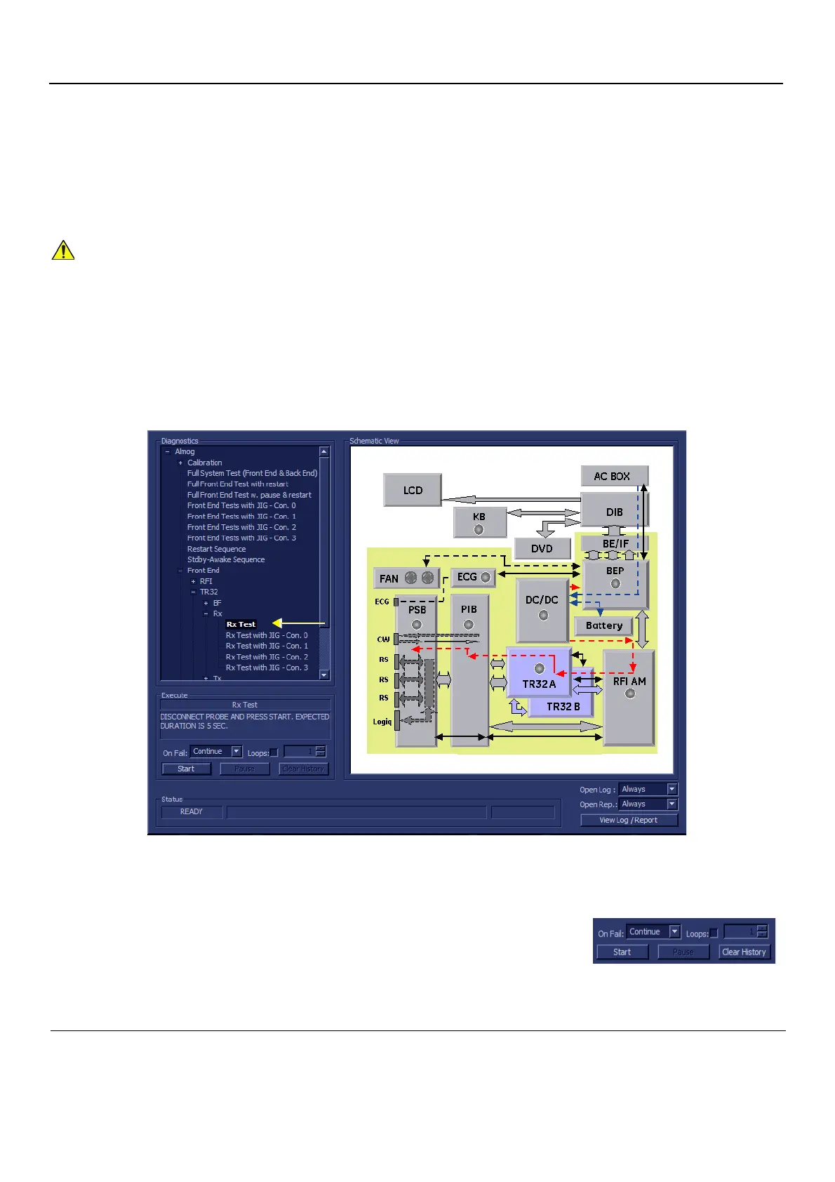
1.) In the Diagnostic Test window, trackball to Rx Test in the list of RX tests available for selection from
the Diagnostic Test Tree (see Figure 7-33 "Rx Test" on page 7-58) and press Set. The RX Test
name is displayed under Execute; the relevant system components to be tested are highlighted light
blue in the Schematic View (TR32A. TR32B), as shown below:
2.) As indicated in the Special Instructions area, disconnect any probes currently connected to the
system and make sure that nothing is touching the probe connectors.
3.) Under the Special Instructions area, activate the Loops checkbox
and select the required number of Loops from the combo box.
4.) Adjacent to On Fail, select either Stop or Continue, as required.
Stopping on failure enables you to review a failed test, the
moment it fails. Alternatively, you may prefer testing to continue on failure and later you may review
the report.
In order to access an individual board test, it is necessary to insert the service dongle from system boot-
up and enter the Service Password.
Figure 7-33 Rx Test
 Loading...


