GE
P
ART NUMBER FN091065, REVISION 2 VS5 N AND VS6 N SERVICE MANUAL
Chapter 7 - Diagnostics/Troubleshooting 7-103
PRELIMINARY
7-5-1 Accessing the Monitoring Diagnostic Test Options (cont’d)
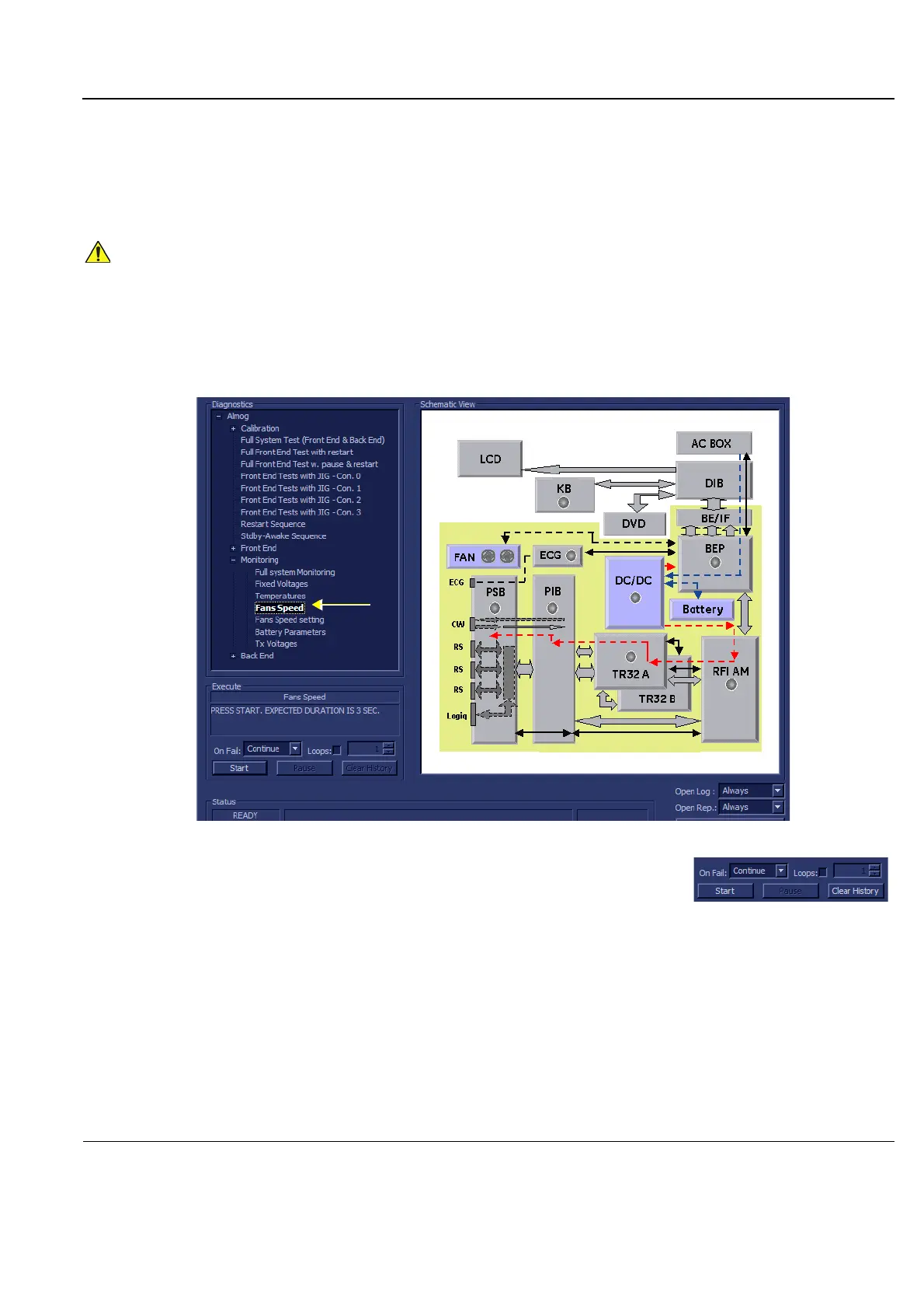
7-5-1-4 Fans Speed Test
NOTE: For a description of this test, refer to the information in 7-2-4-3-4 "Fans Speed Test" on page 7-15.
1.) In the Diagnostic Test window, trackball to Fans Speed in the list of Monitoring tests available for
selection from the Diagnostic Test Tree (see Figure 7-69 "Fans Speed Test" on page 7-103) and
press Set. The Fans Speed Test name is displayed under Execute; the relevant system
components to be tested are highlighted light blue in the Schematic View (AC/DC, Battery, PS), as
shown below:
2.) Under the Special Instructions area, activate the Loops checkbox
and select the required number of Loops from the combo box.
3.) Adjacent to On Fail, select either Stop or Continue, as required.
Stopping on failure enables you to review a failed test, the moment
it fails. Alternatively, you may prefer testing to continue on failure and later you may review the
report.
4.) Trackball to the Start button and press Set.
The Fans Speed Test commences. While the test proceeds, the name of the test currently in
progress (Fans Speed) is displayed in the Execute field and the current Loop # and specific test are
shown below. The messages Init Done and Please Wait are displayed beside the progress bar in
the Status area.
As the testing sequence progresses, the progress bar will advance to reflect the test progress.
Status indicators in the Data Flow map corresponding to the various system components will be
highlighted in the appropriate color to indicate the current test status, as follows:
In order to access an individual board test, it is necessary to insert the service dongle from system boot-
up and enter the Service Password.
Figure 7-69 Fans Speed Test
 Loading...


