GE
P
ART NUMBER FN091065, REVISION 2 VS5 N AND VS6 N SERVICE MANUAL
Chapter 7 - Diagnostics/Troubleshooting 7-105
PRELIMINARY
7-5-1 Accessing the Monitoring Diagnostic Test Options (cont’d)
• If the test fails, repeat the Fan Speed Test.
• If errors were identified but the results were marginal, perform calibration, as described in
“DC Offset Calibration” on page 7-27, and then repeat the test.
• If errors were identified and the results were not marginal, verify that all system cables and
boards are connected (not misplaced) and functioning properly, as described in Chapter 5 -
Components and Function (Theory).
If the problem persists, this indicates that either the specific board you tested is faulty or that
another board that supports the operation of this board is faulty. Contact your local
GE HEALTHCARE field engineer for assistance.
10.)Trackball to the Exit button and press Set to close the View Test Log dialog box.
11.)Press the <Esc> button on the keyboard to close the Diagnostic Test Window.
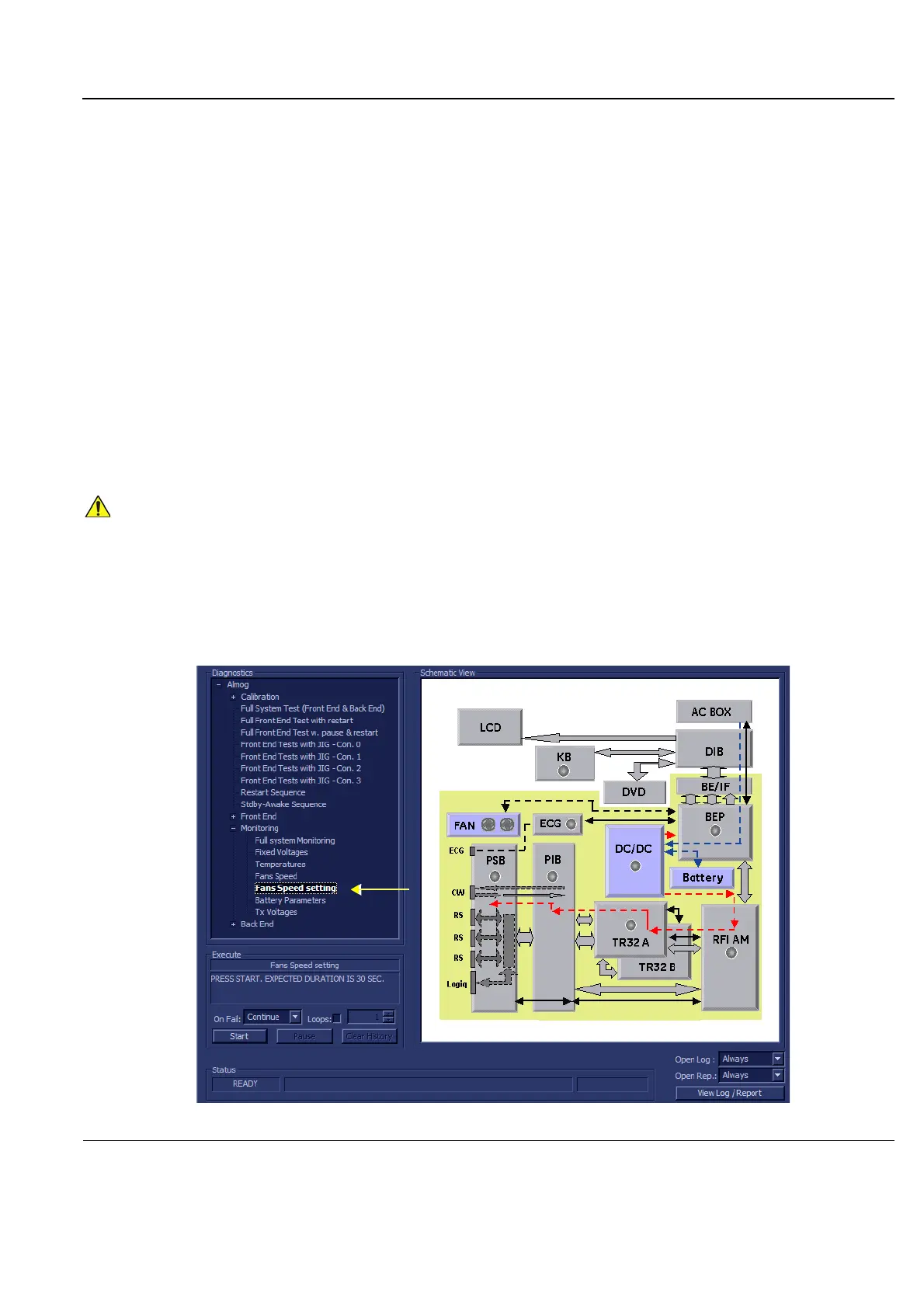
7-5-1-5 Fans Speed Setting Test
NOTE: For a description of this test, refer to the information in “Fans Speed Setting Test” on page 7-15.
1.) In the Diagnostic Test window, trackball to Fans Speed Setting in the list of Monitoring tests
available for selection from the Diagnostic Test Tree (see Figure 7-71 "Fans Speed Setting Test" on
page 7-105) and press Set. The Fans Speed Test name is displayed under Execute; the relevant
system components to be tested are highlighted light blue in the Schematic View (AC/DC, Battery,
PS), as shown below:
In order to access an individual board test, it is necessary to insert the service dongle from system boot-
up and enter the Service Password.
Figure 7-71 Fans Speed Setting Test
 Loading...


