GE
P
ART NUMBER FN091065, REVISION 2 VS5 N AND VS6 N SERVICE MANUAL
Chapter 8 - Replacement Procedures 8-153
PRELIMINARY
8-6-9 PIB (Probe Interface Board) Board Replacement Procedure
8-6-9-1 Tools
Use the appropriate flat and Phillips-type screwdrivers as indicated in the PIB replacement procedure.
8-6-9-2 Time Required
10 minutes
8-6-9-3 Preparation
Shut down the Vivid S5 N or Vivid S6 N ultrasound unit, as described in 4-2-3 "Power Shut Down" on
page 4-7.
8-6-9-4 PIB Board Removal Procedure
1) Remove the system left and right side covers, as described in the “Left Side Cover Removal
Procedure” on page 8-6 and “Right Side Cover Removal Procedure” on page 8-5.
2) Remove the system front cover, as described in the “Front Cover Removal Procedure” on page 8-17.
3) Remove the cabinet cage assembly from the system, open the cage and carefully place it on a
stable surface, as described in the “Cabinet Cage Assembly Opening and Removal Procedure” on
page 8-109.
4.) Unfold the cabinet cage assembly, as described in “Opening and Removing the Cabinet Cage
Assembly” on page 8-109 (see step 11 on page 8-112).
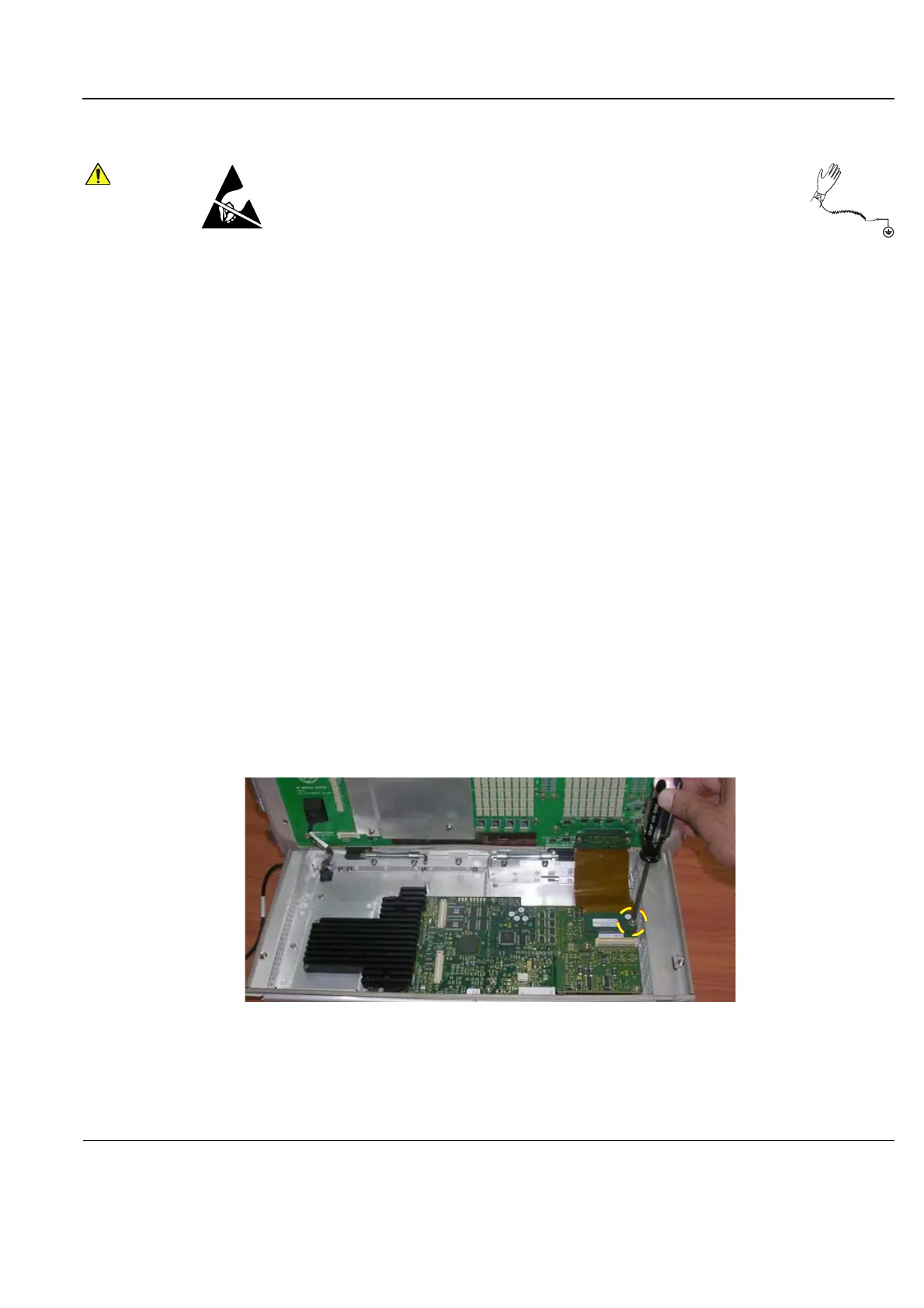
5) Remove the screw that secures the PIB-to-PSB flex cable in position (Figure 8-188).
When performing these procedures, take precautions to avoid damage of
electrostatic-sensitive components. Always have the ESD wrist strap
connected either to the DIB chassis or to the GND plug at the rear of the
scanner, and to your hand.
If a battery is present, first remove the battery as it contains stored energy.
Refer to “Battery Removal Procedure” on page 8-116.
Figure 8-188 Unscrewing the PIB-to-PSB Flex Cable
 Loading...


