GE
P
ART NUMBER FN091065, REVISION 2 VS5 N AND VS6 N SERVICE MANUAL
8-190 Section 8-7 - Mechanical Components Replacement Procedures
PRELIMINARY
8-7-1 Foot Rest Replacement Procedure (cont’d)
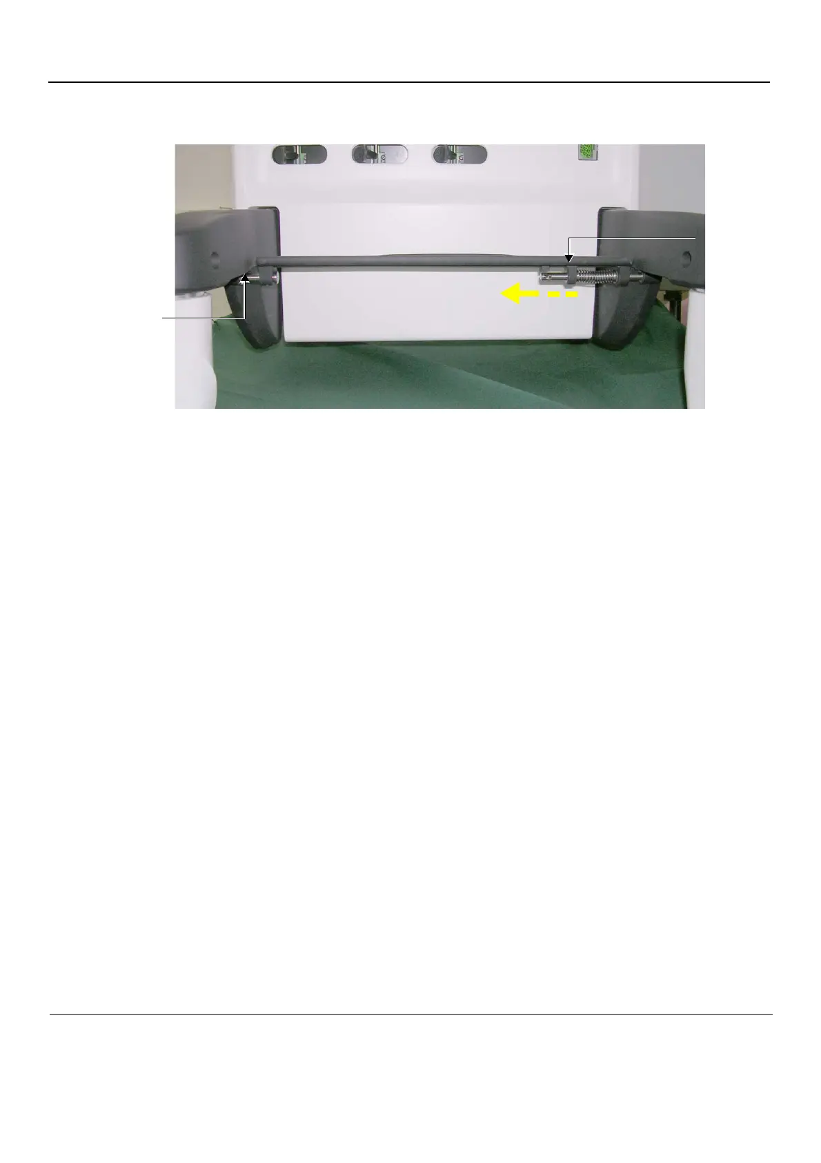
2.) Release the other side of the foot rest from the securing pin on the left side - see Figure 8-239.
3.) Remove the Foot Rest.
8-7-1-4 Foot Rest Installation Procedure
1) Position a new Foot Rest at the front of the system, between the wheelbase.
2) Fit the left side of the Foot Rest into the securing pin on the left side of the chassis - refer to Figure
8-239.
3.) Insert the right side of the footrest into the right side of the wheelbase; close the spring-loaded bolt
hinge (located underneath the foot rest on the right side) to fasten the footrest securely in position
on the wheelbase - refer to Figure 8-239 on page 8-190.
4.) Proceed to perform the following functionality tests:
- 4-3-3-4 "Front Wheel Function Test" on page 4-36
- 4-3-3-5 "Rear Wheel Function Test" on page 4-36
Figure 8-239 Bolt Hinge Securing Foot Rest to Wheelbase
Slide hinge in this direction
Bolt Hinge
Securing Pin
 Loading...


