GE
P
ART NUMBER FN091065, REVISION 2 VS5 N AND VS6 N SERVICE MANUAL
Chapter 8 - Replacement Procedures 8-105
PRELIMINARY
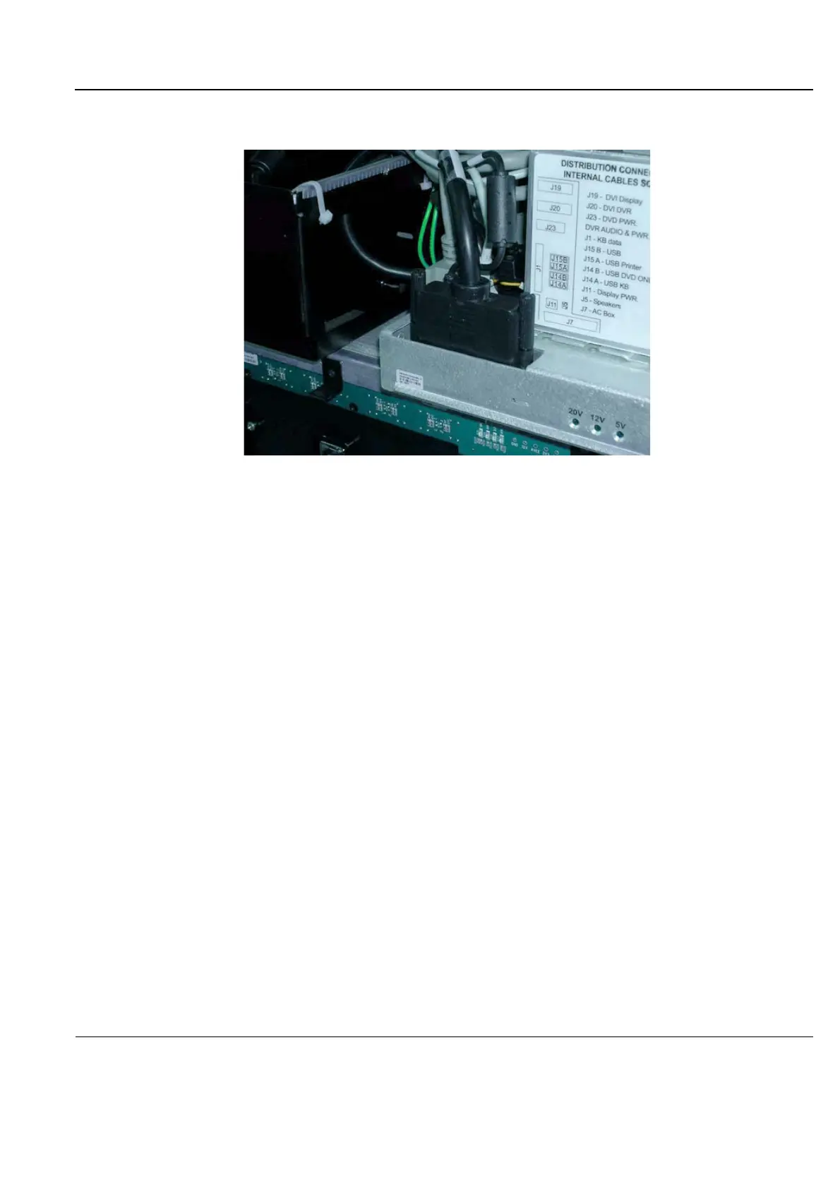
3.) To complete the procedure, disconnect the relevant cables from the Distribution Interface Board
(DIB); see Figure 8-126
.
8-5-1-4 Keyboard and Monitor Cable Installation Procedure
1.) Re-connect all the relevant cables (including the new Keyboard power cable and Monitor cable) to
the Distribution Interface Board (DIB); see Figure 8-126
.
2.) Re-fit the central metal bracket, as indicated in Figure 8-125.
3.) Return the system covers, as described in the following procedures (see also):
• “Front Cover Installation Procedure” on page 8-19
• “Right Side Cover Installation Procedure” on page 8-5
• “Left Side Cover Installation Procedure” on page 8-7
4.) Proceed to route the following four cables up through the aperture in the base of the Keyboard
Interface Assembly, working in the following order:
a.) LCD power cable - refer to Figure 8-123.
b.) DVI cable - refer to Figure 8-122.
c.) 90° Data - refer to Figure 8-121.
d.) USB cable - refer to Figure 8-120.
5.) Fasten the two lower cable securing brackets, as indicated in Figure 8-119.
6.) Return and fasten the two upper cable securing brackets (previously removed), as indicated in
Figure 8-118. (Use a Phillips screwdriver to carefully tighten the screw
s)
Note: Before the next procedure, it is recommended to lean the keyboard interface platform
backwards and to place protective material between the lower arm and the handle, as
indicated in Figure 8-117.
Figure 8-126 Cables Connected to Distribution Interface Board
 Loading...


