GE
P
ART NUMBER FN091065, REVISION 2 VS5 N AND VS6 N SERVICE MANUAL
8-88 Section 8-3 - Control Console Components Replacement Procedures
PRELIMINARY
8-4-11 LEDs and Soft Menu Board Replacement (Old-type OP)
The procedures described in this section are applicable to any Vivid S5 N / Vivid S6 N system with the
old-type Operator Panel
8-4-11-1 Tools
Use the appropriate flat screwdriver and T10 Torx screwdriver (T8 may also be used), as indicated in
the LEDs and Soft Menu Board replacement procedure.
8-4-11-2 Preparation
Shut down the Vivid S5 N or Vivid S6 N ultrasound unit, as described in 4-2-3 "Power Shut Down" on
page 4-7.
8-4-11-3 LEDs and Soft Menu Board Removal Procedure
1.) Remove the Keyboard Assembly, as described in the “Keyboard Assembly Removal Procedure” on
page 8-39.
2.) Remove all the TGC Keycaps, as described in “Alphanumeric Keycap Removal Procedure” on
page 8-90.
3.) Carefully place the Keyboard Assembly upside-down on a flat, clean, stable surface.
4.) Remove the Keyboard Bottom Cover, as described in the “Keyboard Bottom Cover Removal
Procedure” on page 8-59.
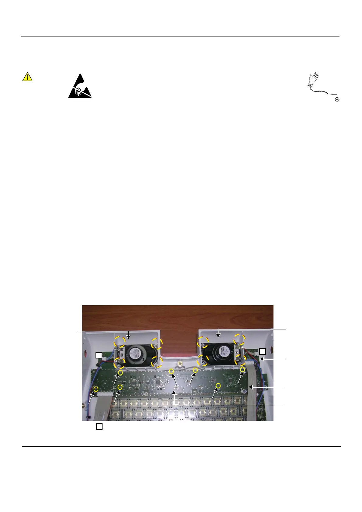
5.) Disconnect the two flat cable connectors (one connected to the LED board and one to the Soft
Menu), as indicated (labelled C) in Figure 8-102. (Leave the flat cable in position).
6.) Loosen and remove the four star-shape screws that fasten each of the LEDs and Sensor boards in
position, as shown in Figure 8-102.
When performing these procedures, take precautions to avoid damage of
electrostatic-sensitive components. Always have the ESD wrist strap
connected either to the DIB chassis or to the GND plug at the rear of the
scanner, and to your hand.
If a battery is present, first remove the battery as it contains stored energy.
Refer to “Battery Removal Procedure” on page 8-116.
Figure 8-102 LEDs and Soft Menu Board Removal
LEDs and Sensor Board
LEDs and Sensor Board
Soft Menu Board
Loosen GND Cable
Loosen GND Cable
C
Note: = cable to be disconnected
C
C
 Loading...


