GE
P
ART NUMBER FN091065, REVISION 2 VS5 N AND VS6 N SERVICE MANUAL
8-172 Section 8-6 - Lower Section Components Replacement Procedures
PRELIMINARY
8-6-13 Sub-woofer Assembly Replacement Procedure
8-6-13-1 Tools
Use the appropriate flat and Phillips-type screwdrivers and a wire cutter as indicated in the
Sub-woofer replacement procedure.
8-6-13-2 Preparation
Shut down the Vivid S5 N or Vivid S6 N ultrasound unit, as described in 4-2-3 "Power Shut Down" on
page 4-7.
8-6-13-3 Sub-woofer Removal Procedure
1) Remove the system left and right side covers, as described in the “Left Side Cover Removal
Procedure” on page 8-6 and “Right Side Cover Removal Procedure” on page 8-5.
2) Remove the system front cover, as described in the “Front Cover Removal Procedure” on page 8-17.
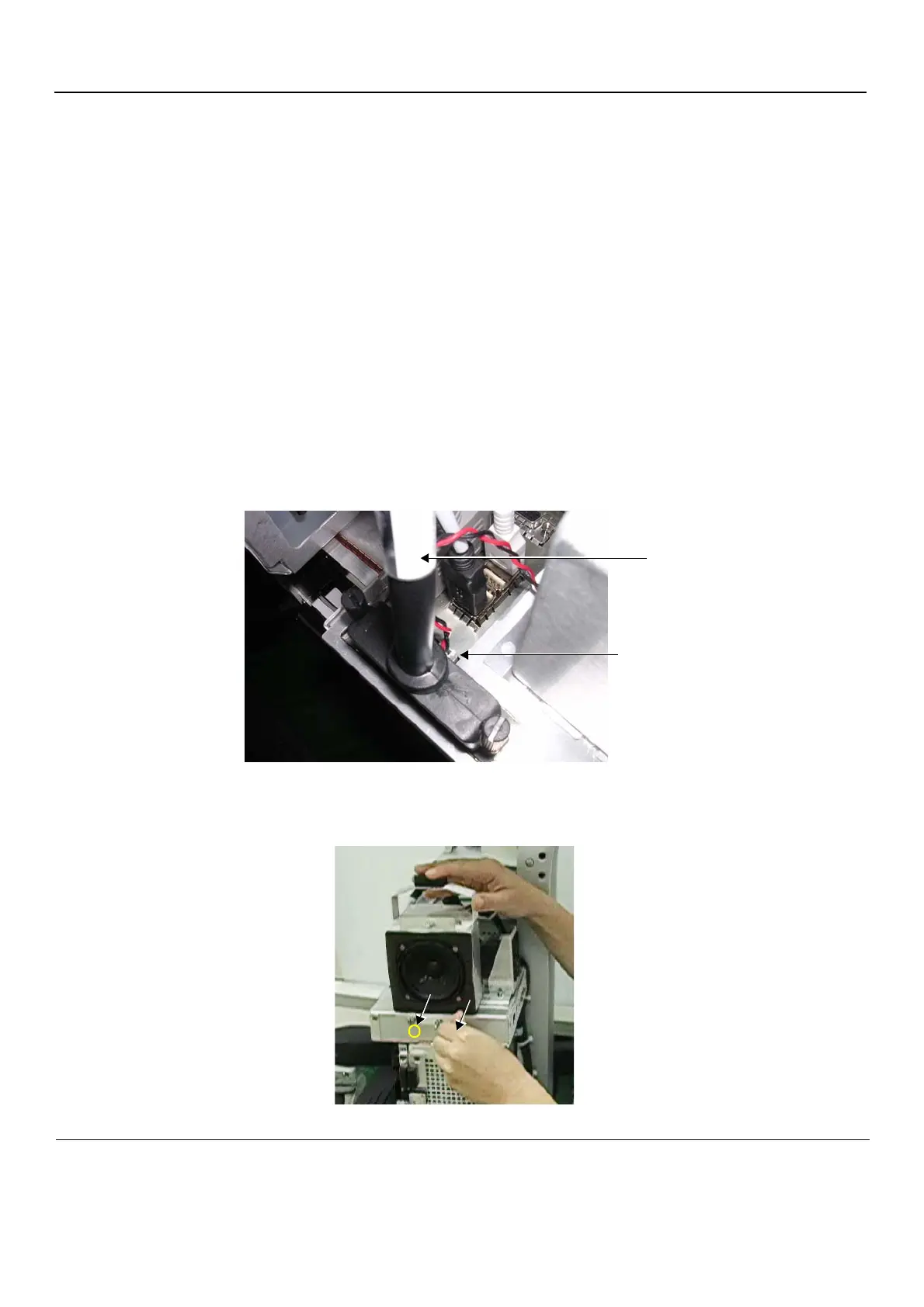
3) Disconnect the D-Type power cable from the DIB (see Figure 8-215).
4) Disconnect the Sub-woofer cable from the cable connection on the AC Distribution box - refer to
Figure 8-215.
5.) Loosen the two screws securing the Sub-woofer to the top of the AC Distribution box.
Figure 8-215 Sub-woofer Cable Connection
Figure 8-216 Loosening the Securing Screws
Disconnect Sub-woofer cable here
D-Type power cable
 Loading...


