GE
P
ART NUMBER FN091065, REVISION 2 VS5 N AND VS6 N SERVICE MANUAL
8-72 Section 8-3 - Control Console Components Replacement Procedures
PRELIMINARY
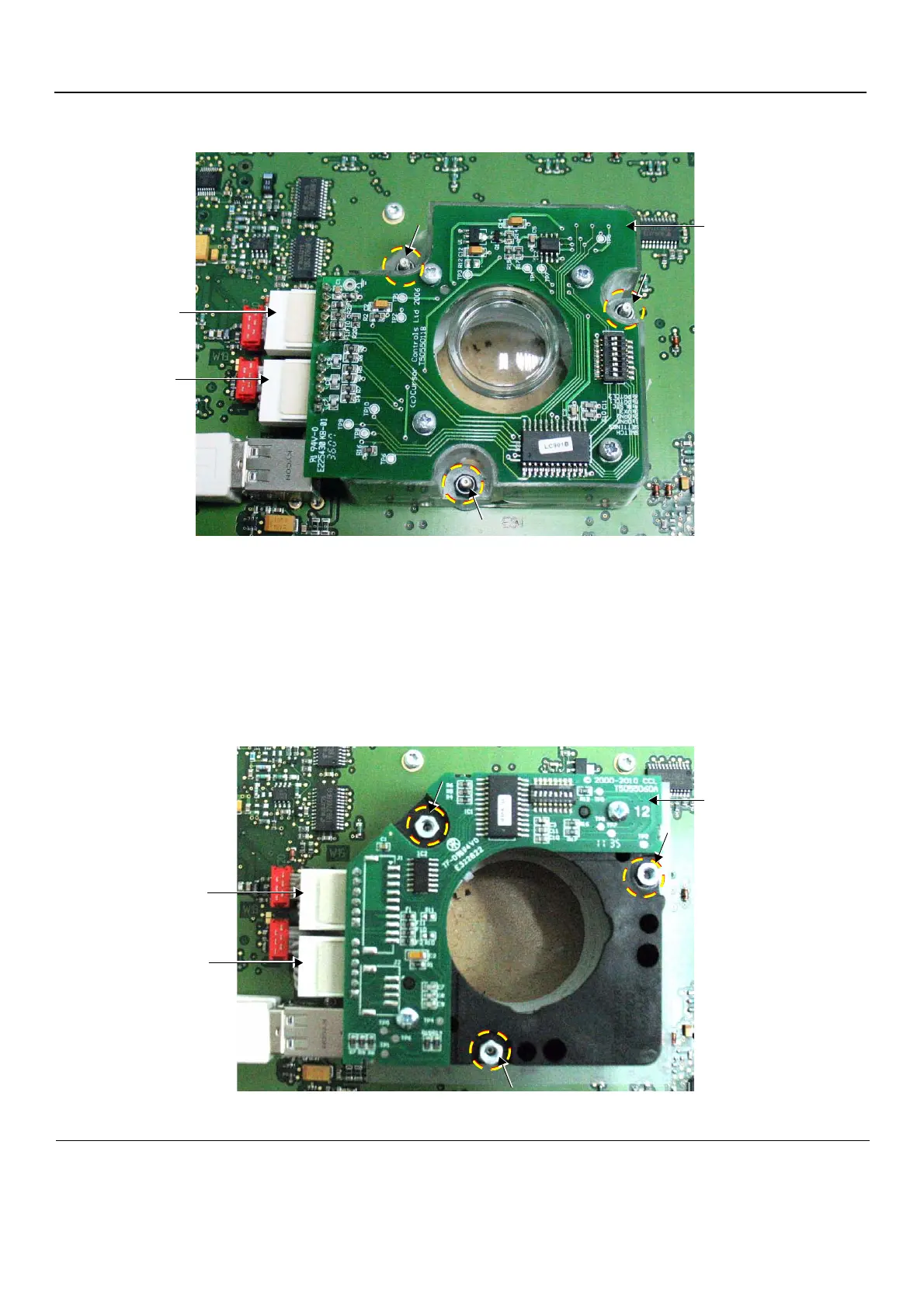
6.) Remove each of the three nuts from the Trackball Board and housing, as indicated in Figure 8-88
7.) Disconnect the two cable connectors, as indicated in Figure 8-88.
8.) Lift the Trackball Board upwards and remove it from the assembly.
8-4-5-4 Mechanical Trackball and Housing Installation Procedure
1.) Place a flat washer on each of the three retaining screws extending from the base board.
2.) Carefully place the new Mechanical Trackball Board and Housing in position on the keyboard
assembly (refer to Figure 8-89).
Figure 8-88 Trackball Board and Housing Removal
Figure 8-89 Trackball Board and Housing Installation
Cable
Connector
Cable
Connector
Trackball Board
and Housing
Cable
Connector
Cable
Connector
Trackball Board
and Housing
 Loading...


