GE
P
ART NUMBER FN091065, REVISION 2 VS5 N AND VS6 N SERVICE MANUAL
2-4 Section 2-2 - Console Requirements
PRELIMINARY
2-2-5 Electrical Requirements
NOTE: GE HEALTHCARE requires a dedicated mains power line and Ground for the proper operation
of its Ultrasound equipment. This dedicated power line shall originate at the last distribution
panel before the system.
Sites with a mains power system with defined Neutral and Live:
The dedicated line shall consist of one phase, a neutral (not shared with any other circuit), and a full
size Ground wire from the distribution panel to the Ultrasound outlet.
Sites with a mains power system without a defined Neutral:
The dedicated line shall consist of one phase (two lines), not shared with any other circuit, and a full
size Ground wire from the distribution panel to the Ultrasound outlet.
NOTE: Please note that image artifacts can occur, if at any time within the facility, the Ground from the
main facility's incoming power source to the Ultrasound unit is only a conduit.
2-2-5-1 Vivid™ S5 N and Vivid™ S6 N Power Requirements
Electrical specifications for the Vivid™ S5 N and Vivid™ S6 N system are as follows:
2-2-5-2 Inrush Current
Inrush current is not a factor for consideration, due to the inrush current limiting properties of the power
supplies.
2-2-5-3 Site Power Outlets
A dedicated AC power outlet must be within reach of the unit without requiring the use of extension
cords. Other outlets adequate for the external peripherals, medical and test equipment required to
support this unit must also be present and located within 1 m (3.2 ft) of the unit. Two dedicated outlets
for peripherals - located at the rear of the system - should be used for all peripherals attached to the
system, unless otherwise indicated. Electrical installation must meet all current local, state, and national
electrical codes.
2-2-5-4 Mains Power Plug
The Vivid™ S5 N and Vivid™ S6 N portable ultrasound scanner is supplied with a mains power plug,
as standard. In the event that the unit arrives without a power plug, or with the wrong plug, contact your
GE dealer. When necessary, the installation engineer will supply the appropriate power plug to meet
the applicable local regulations.
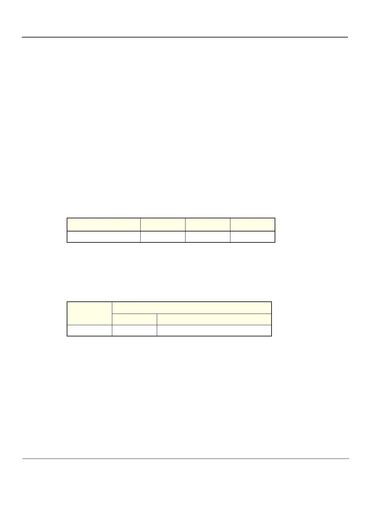
Table 2-3 Electrical Requirements
Input Voltage Tolerances Op. Current Frequency
100V AC to 240V AC ±10% 0.5 to 1A 50-60 Hz
Table 2-4 Inrush Current
Voltage
Inrush Current
Console Only Console with all Peripherals
240 V 2.3 A 4.5 A
 Loading...


