5
BRIDGE MODE SETTING SCREEN
5-97
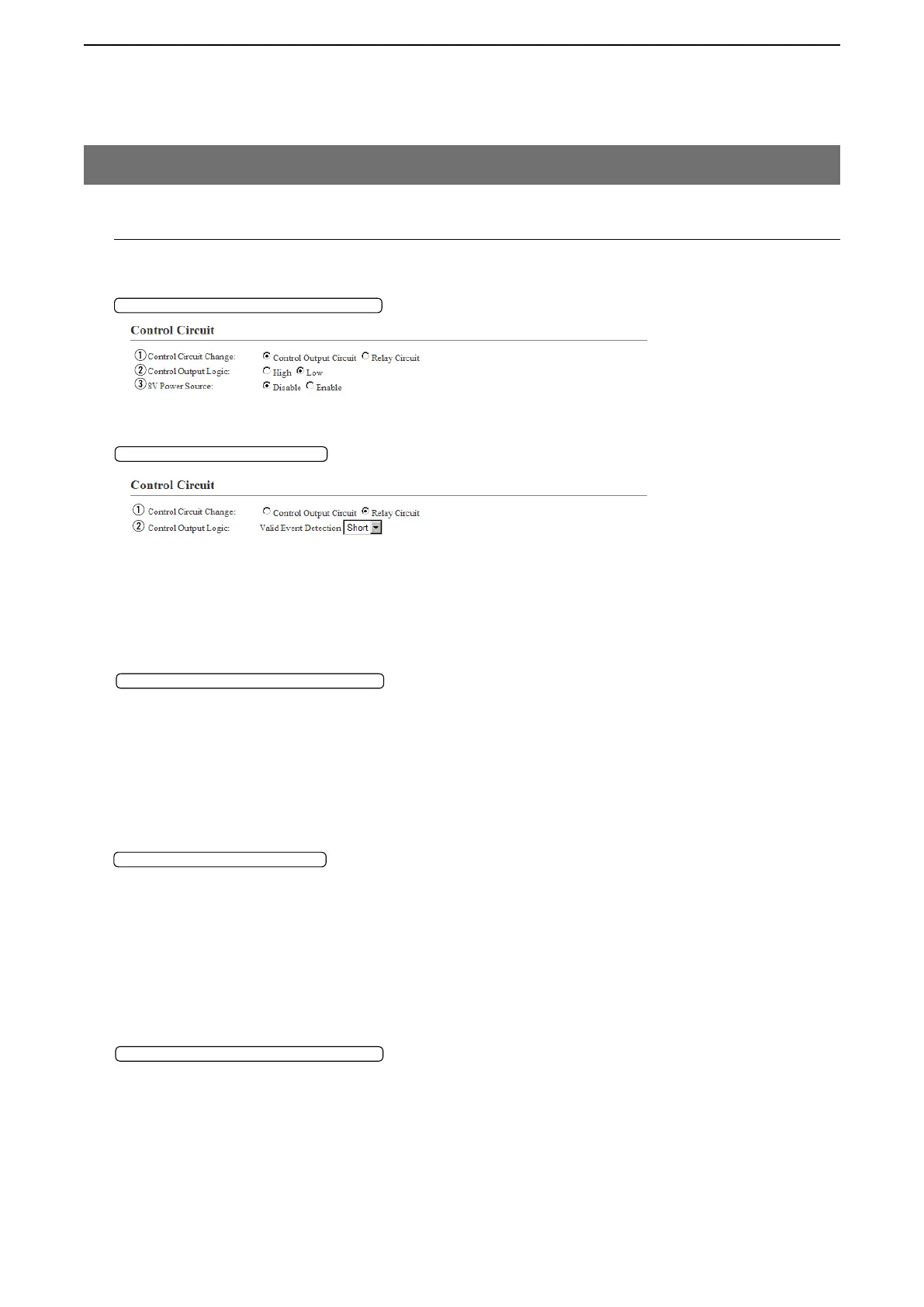
M Control Circuit
Configure the details for the device connected to the [EXT1]/[EXT2] port.
q Control Circuit Change … Select the control circuit type. (Default: Control Output Circuit)
w Control Output Logic …… Select the activate state. (Default: Low)
• High: The squelch line becomes “High” while receiving no signal. (Active
High)
• Low: The squelch line becomes “Low” while receiving no signal. (Active
Low)
w Control Output Logic …… Select the port state. Relay output terminal (B1/B2 terminal) is short circuit or
open circuit. (Default: Short)
When the audio signal is output, the control signal is also output.
• Short: The squelch line becomes “High” while receiving no signal. (Active
High)
• Open: The squelch line becomes “Low” while receiving no signal. (Active
Low)
e 8V Power Source ………… Select “Enable” to supply the 8 V to the microphone, which is connected to
the external output terminal (B1/B2 terminal). (Default: Disable)
Specification: Less than 30 mA
8. [Port Settings] Menu (continued)
Control Circuit Change:Control Output Circuit
Control Circuit Change:RelayCircuit
Control Circuit Change:Control Output Circuit
Control Circuit Change:Control Output Circuit
Control Circuit Change:RelayCircuit
[Port Settings]–[EXT Output 1 (EXT1)/EXT Output 2 (EXT2)]