3
CONVERTER MODE APPLICATION
3-19
4. Making an emergency announcement (continued)
1
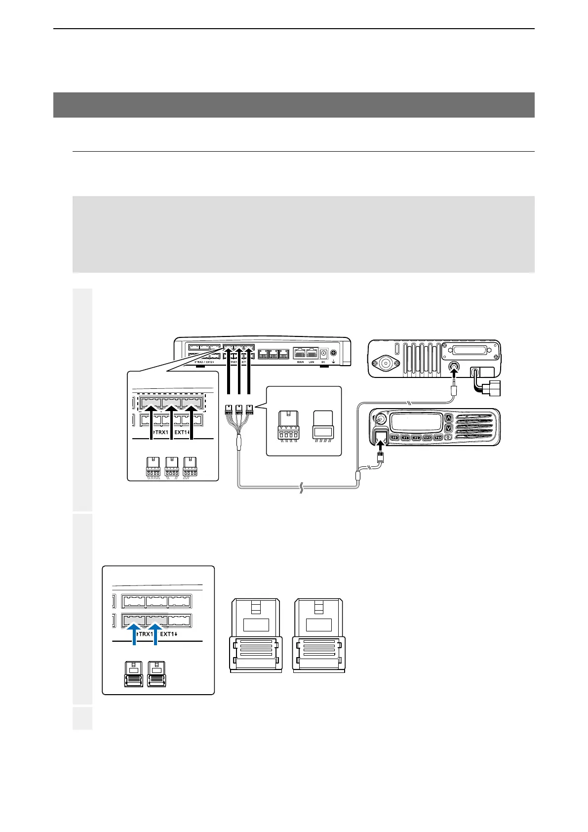
Make a cable the length you need, with two connectors wired as shown, and the appropriate connectors for
your audio device. Then connect it to the [EXT1] on the VE-PG3 and then to your audio device.
• See Section 8 for the port details.
2
3
VE-PG3 (Rear view)
Icom’s transceiver
(IC-F5060/IC-F6060 series)
(Rear view)
(Front view)
To the external speaker jack
To the microphone connector
LINE2
LINE1
PHONE
• The [TRX1] and [TRX2] ports (upper slots) accept the OPC-2275 connectors.
However, follow the example to correctly connect the transceiver to ONLY the [TRX1] slot.
ABC
Be sure to insert the
connectors top side up.
Bottom
To p
A
1234
OPC-2275
AABC
To [TRX1] (Upper slot)
BA
To [EXT1] (lower slot)
12 34 12 34
B
A1 A2 A3 A4 B1 B2 B3 B4
12 34
A
12 34
2. Connection
Set the transceiver channel, volume level, TX output power, and other necessary settings, before connecting to the
VE-PG3.
Connect the VE-PG3 and the transceiver using the OPC-2275 cable.
• Verify that both the VE-PG3 and the transceiver are turned OFF when connecting the cable.
When all the connections are completed, turn ON the transceiver and VE-PG3’s power.
NOTE:
• Full duplex communication is impossible.
Communicate with each other by taking turns speaking.
• Pause briefly before you speak, to confirm your party has finished speaking.
• The communication route will be disconnected when the IP telephone's handset is put on the hook, or the VE-PG3 receives no
audio for the preset time (default: 15 seconds).
Connector pin configuration
A1: Audio output (OUT)
A2: Audio output ground
A3: Audio input (IN)
A4: Audio input ground
B3: Control input
B4: Control ground