6
CONVERTER MODE SETTING SCREEN
6-102
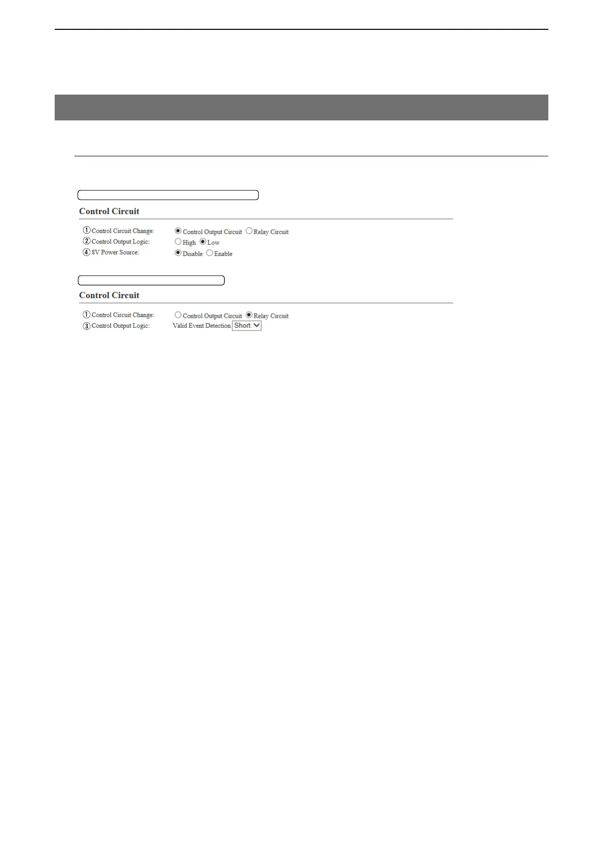
M Control Circuit (EXT Output)
Configure the details for the control circuit connected to the [EXT1]/[EXT2] port.
9. [Port Settings] Menu (continued)
[Port Settings]–[EXT Output 1 (EXT1)/
EXT Output 2 (EXT2)]
Control Circuit Change: Control output Circuit
Control Circuit Change: Relay Circuit
q Control Circuit Change … Select the control circuit type. (Default: Control Output Circuit)
Note: When “Relay Circuit” is selected, “Half-Duplex” cannot be selected in
[Communication Control] on the “Serial Communication” field.
w Control Output Logic …… Select the activate state. (Default: Low)
e Control Output Logic …… Select the port state. Relay output terminal (B1/B2 terminal) is short circuit or
open circuit. (Default: Short)
When the audio signal is output, the control signal is also output.
r 8V Power Source ………… Select “Enable” when supply the 8 V to the EXT Output terminal (B2/B4
terminal), when a microphone is connected. (Default: Disable)
Current limit: Less than 30 mA
Note: When “Enable” is selected, “Half-Duplex” cannot be selected in
[Communication Control] on the “Serial Communication” field.