3
CONVERTER MODE APPLICATION
3-34
7. Connecting to the Bridge mode's VE-PG3 (continued)
3. Operation
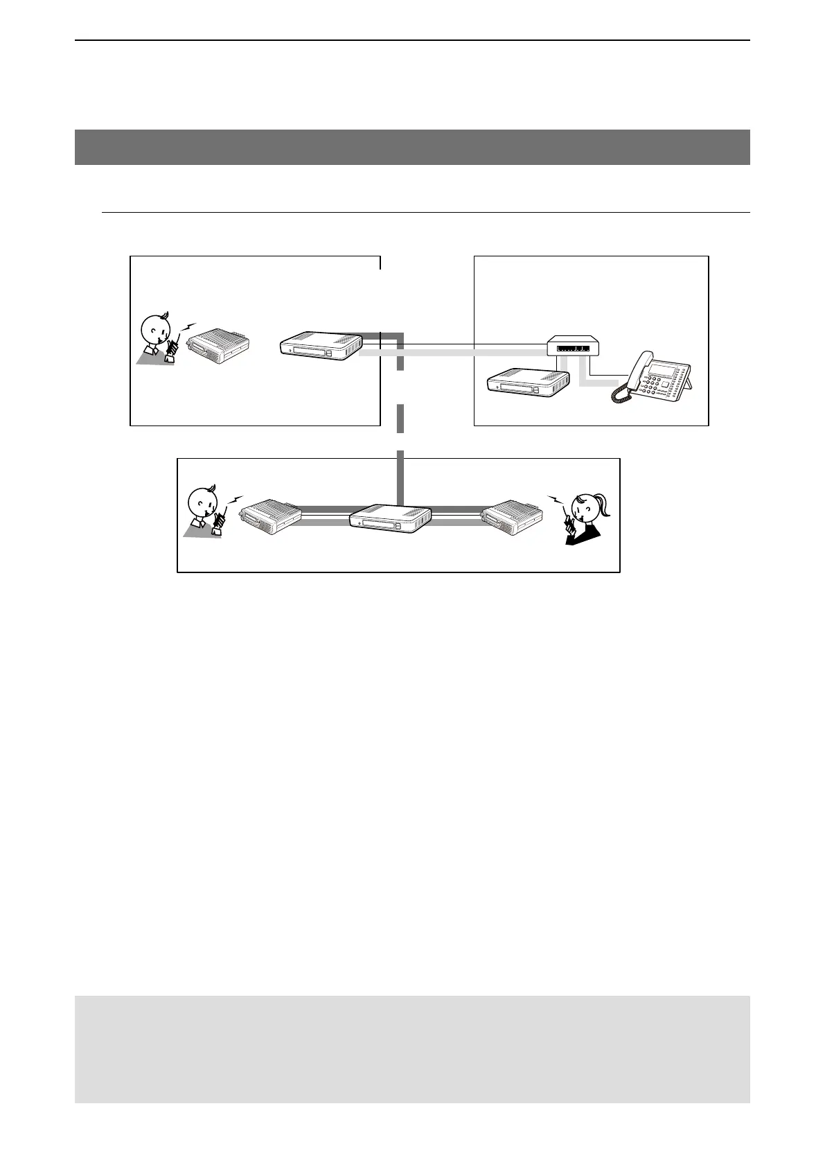
The IP phone in area B dials 51 to call radio A1, and the call is also routed to C1 and D1 in area C.
Area C
Area AArea B
An example of the connection in the Converter mode and Bridge mode
Radio A
Radio A1
VE-PG3
(192.168.0.2)
VE-PG3
(192.168.0.3)
[TRX1]
[LAN]
Extension No.
301
Extension No.
401
Radio C
Radio C1
Radio D1
VE-PG3
(192.168.0.4)
[TRX1][TRX2]
Radio D
Bridge Connection
IP phone No.
31
[Bridge1]
(Multicast)
IP phone No.
51
Extension No.
501
IP telephone
(KX-UT Series)
HUB
[The procedure to call radio in area A. (The call is
also routed to C1 and D1 in area C.
)]
q
Area B
Person on the IP telephone: Take the handset off the hook, dial 51 (IP phone No.), and then speak into the tele-
phone at a normal voice level.
w
Area A
Radio A1 receives the call. Push Radio A1’s [PTT] to respond to the call from the IP phone in area B.
e
Area C
The call is routed to all radios on the same channel with Radio C and Radio D.
[The procedure to call radio in area A. (The call is NOT
routed to C1 and D1 in area C.
)]
q
Area B
Person on the IP telephone: Take the handset off the hook, dial 31 (IP phone No.), and then speak into the tele-
phone at a normal voice level.
w
Area A
Radio A1 receives the call. Push Radio A1’s [PTT] to respond to the call from the IP phone in area B.
e
Area C
The call is NOT routed to radio in area C.
NOTE:
• Full duplex communication is impossible.
Communicate with each other by taking turns speaking.
• Pause briefly before you speak, to confirm your party has finished speaking.
• The communication route will be disconnected when the IP telephone's handset is put on the hook, or the VE-PG3 receives no
audio for the preset time (default: 15 seconds).