2
BRIDGE MODE APPLICATION
2-8
3. Using the Mixing function
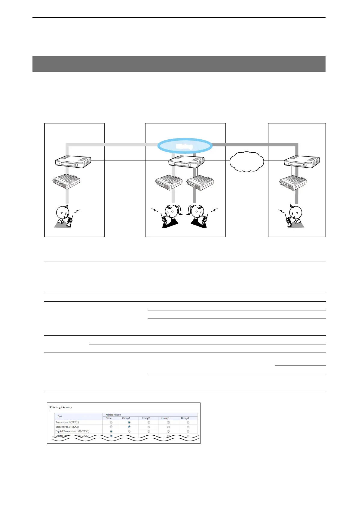
The mixing function mixes conversations from different Areas. As shown in the figure below, the Area A radio users
can talk to the Area B and relayed to the Area C.
• In this example, the audio signal of [TRX1] port and [TRX2] port (VE-PG3 in Area B) are mixed as illustrated
below.
Menu Item Setting Screen Setting Item Item Name Value
Operating Mode Operating Mode Operating Mode Operating Mode Bridge
IP Communication Mode IP Communication Mode Unicast
Mixing Group*
Transceiver 1(TRX1),
Transceiver 2(TRX2)
Port Settings Transceiver 1 (TRX1) Transceiver Model: Transceiver Model IC-F5060/F6060
Transceiver 2 (TRX2) Transceiver Model: Transceiver Model IC-F5060/F6060
Bridge Connection Bridge Connection Point Bridge Connection Point Connection IP Address TRX1:192.168.0.2
TRX2:192.168.0.4
List of Bridge Connection
Point Entries
Connection Status During Transmit
Area A Area B
An example of communication with the Mixing function
Radio A1 Radio C1
Radio B1
VE-PG3
(192.168.0.2)
[TRX1]
[LAN] [LAN]
Area C
VE-PG3
(192.168.0.4)
[TRX2]
Radio D1
Radio A
Radio C
Unicast Unicast
IP
Network
Radio B
[TRX1]
Radio D
[TRX2]
VE-PG3
(192.168.0.3)
Mixing
Mixing
VE-PG3 (Area B)
1. Configuration
Access the VE-PG3 setting screen, and set the items as shown below.
• Configure the VE-PG3 in Area A and C, referring to “Operation in the Unicast mode.“
*Enter the round marks to the “Group1” field in the Transceiver 1 (TRX1) and Transceiver 2 (TRX2) rows.