2
BRIDGE MODE APPLICATION
2-13
1
2
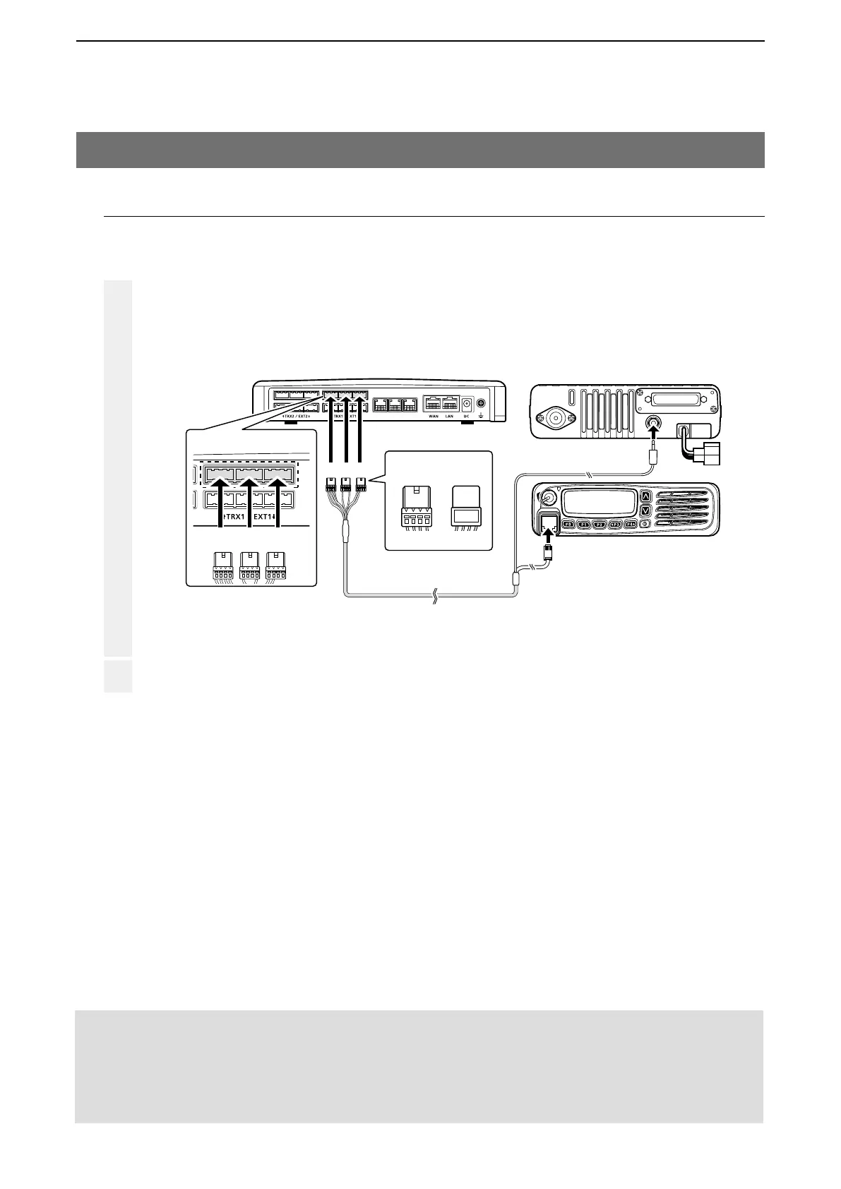
VE-PG3 (Rear view)
Icom’s transceiver
(IC-F5060/IC-F6060 series)
(Rear view)
(Front view)
To the external speaker jack
To the microphone connector
LINE2
LINE1
PHONE
• The [TRX1] and [TRX2] ports (upper slots) accept the OPC-2275 connectors,
however, follow the example to correctly connect the transceiver to ONLY the [TRX1] on the VE-PG3.
ABC
Be sure to insert the
connectors top side up.
Bottom
To p
A
1234
OPC-2275
AABC
To [TRX1] (Upper slots)
4. Operating in the NXDN Conventional mode (continued)
3. Connection
Set the transceiver channel, volume level, TX output power, and other necessary settings, before
connecting to the VE-PG3.
Connect the VE-PG3 and the transceiver, using the appropriate optional cable.
• Verify that both the VE-PG3 and the transceiver are turned OFF when connecting the cable.
When all the connections are finished, turn ON the transceiver and VE-PG3’s power.
NOTE:
• Verify that both the radio and the VE-PG3 are turned OFF when connecting or disconnecting the transceiver.
• Keep the radio away from a PC, AC adaptor and other electronic equipment. The noise emitted from those equipment may
interfere with the radio.
• When operating the radio, do not transmit near the IP telephone.