3
CONVERTER MODE APPLICATION
3-24
5. Emergency Notice (continued)
1
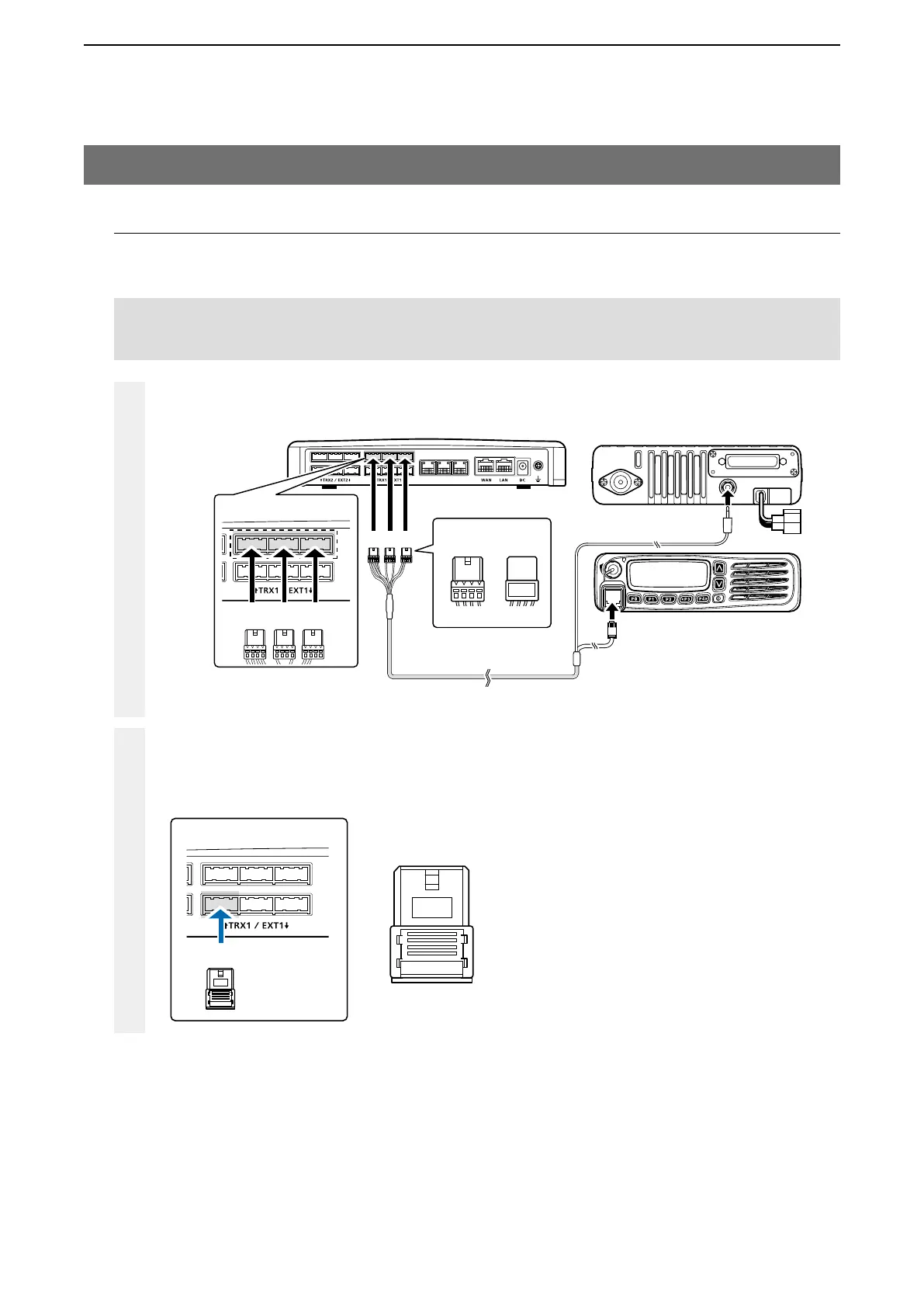
Make a cable the length you need, with the supplied connector wired as shown, and the appropriate con-
nectors for your audio device. Then connect it to the [EXT1] on the VE-PG3 and then to your audio device.
• See Section 8 for the port details.
2
VE-PG3 (Rear view)
Icom’s transceiver
(IC-F5060/IC-F6060 series)
(Rear view)
(Front view)
To the external speaker jack
To the microphone connector
LINE2
LINE1
PHONE
• The [TRX1] and [TRX2] ports (upper slots) accept the OPC-2275 connectors.
However, follow the example to correctly connect the transceiver to ONLY the [TRX1] slot.
ABC
Be sure to insert the
connectors top side up.
Bottom
To p
A
1234
OPC-2275
AABC
To [TRX1] (Upper slot)
2. Connection
Set the transceiver channel, volume level, TX output power, and other necessary settings, before connecting it to
the VE-PG3.
Connect the VE-PG3 and the transceiver, using the OPC-2275 cable.
(Continued on the next page.)
A
To [EXT1] (lower slot)
12 34
A1 A2 A3 A4
A
12 34
NOTE:
• Verify that both the radio and the VE-PG3 are turned OFF when connecting or disconnecting the transceiver.
Connector pin configuration
A1: Audio output (OUT)
A2: Audio output ground
A3: Audio input (IN)
A4: Audio input ground