3
CONVERTER MODE APPLICATION
3-25
5. Emergency Notice
2. Connection (continued)
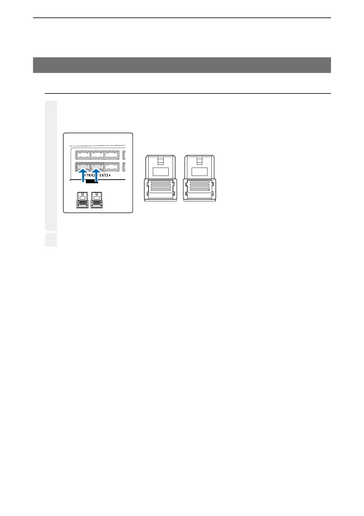
Make a cable the length you need, with two supplied connectors wired as shown, and the appropriate con-
nectors for your audio device. Then connect it to the [EXT2] on the VE-PG3 and then to your audio device.
• See Section 8 for the port details.
3
4
To [EXT2] (lower slot)
BA
12 34 12 34
B
A1 A2 A3 A4 B1 B2 B3 B4
12 34
A
12 34
When all the connections are complete, turn ON the transceiver and VE-PG3’s power.
Connector pin configuration
A1: Audio output (OUT)
A2: Audio output ground
A3: Audio input (IN)
A4: Audio input ground
B3: Control input
B4: Control ground