3
CONVERTER MODE APPLICATION
3-8
2. Using an in-house sound system (continued)
1
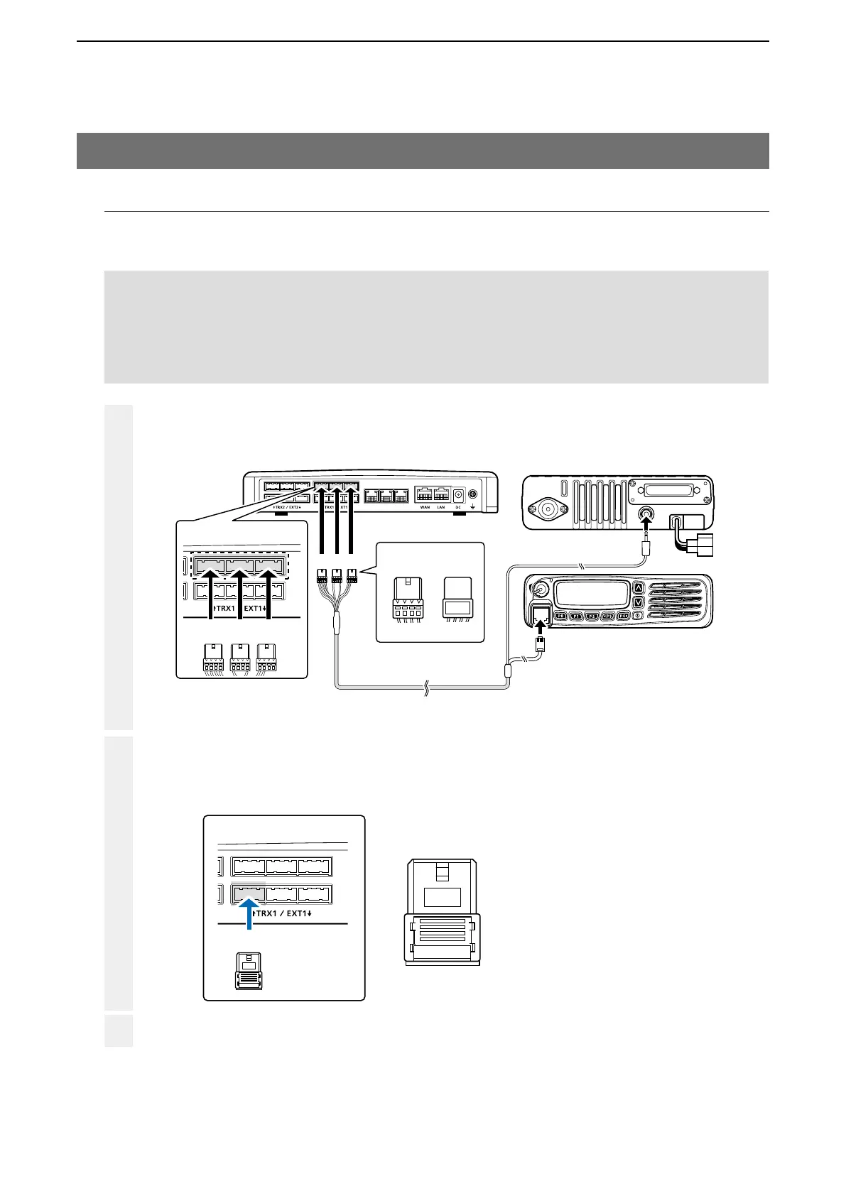
Make a cable the length you need, with an supplied connector wired as shown, and the appropriate connec-
tor for your audio device. Then connect it to the [EXT1] on the VE-PG3 and then to your audio device.
• See Section 8 for port details.
2
3
VE-PG3 (Rear view)
Icom’s transceiver
(IC-F5060/IC-F6060 series)
(Rear view)
(Front view)
To the external speaker jack
To the microphone connector
LINE2
LINE1
PHONE
• The [TRX1] and [TRX2] ports (upper slots) accept the OPC-2275 connectors.
However, follow the example to correctly connect the transceiver to ONLY the [TRX1] slot.
ABC
Be sure to insert the
connectors top side up.
Bottom
To p
A
1234
OPC-2275
AABC
To [TRX1] (Upper slot)
A
To [EXT1] (lower slot)
12 34
A1 A2 A3 A4
A
12 34
A1: Audio output (OUT)
A2: Audio output ground
A3: Audio input (IN)
A4: Audio input ground
2. Connection
Set the transceiver channel, volume level, TX output power, and other necessary settings, before connecting to the
VE-PG3.
When all the connections are completed, turn ON the transceiver and VE-PG3’s power.
Connect the VE-PG3 and the transceiver, using the OPC-2775 cable.
NOTE:
• Verify that both the radio and the VE-PG3 are turned OFF when connecting or disconnecting the transceiver.
• Keep the radio away from a PC, AC adaptor and other electronic equipment. The noise emitted from those equipment
may interfere with the radio.
• When operating the radio, do not transmit near the IP telephone.