3
CONVERTER MODE APPLICATION
3-20
3. Operation
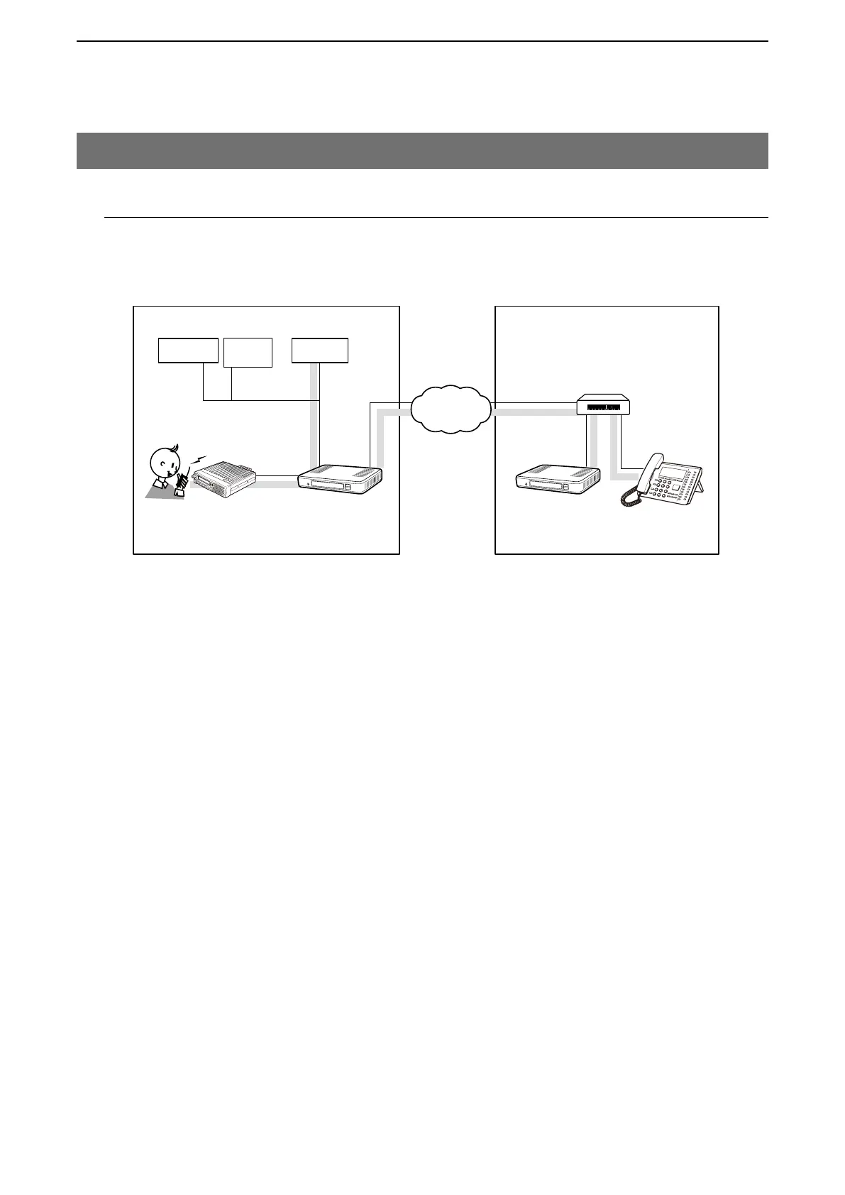
Push [PTT] on Radio A1 to make a regular broadcast. Dial 99 on the IP phone to make an emergency broadcast.
4. Making an emergency announcement (continued)
[ Making a regular broadcast from Radio A1.]
q
Area A
Radio A1’s operator: While holding down [PTT], say
something (example: “Standby for an announce-
ment”) into the microphone at a normal voice level.
• The [TRX1] and [EXT1] ports are internally connected.
w
Area A/B
The announcement from Radio A1 is output to the
external audio device connected to [EXT1], followed
by the “Broadcast start sound.”
e
Area A
When no audio signal is detected for 5 seconds (de-
fault), the route is disconnected, after the “Broadcast
end sound.”
[ Making an emergency broadcast from the external
microphone.]
q
Area A
Turn ON the external switch (connect B3 and B4 ter-
minals).
w
Area A
The announcement from the external microphone
is output to the external audio device connected to
[EXT1] and Radio A1, followed by the “Broadcast
start sound.”
[ Making an emergency broadcast from the IP
phone.]
q
Area B
Person on the IP telephone: Take the handset off the
hook, dial 99.
• The [TRX1] and [EXT1] ports receive the call.
w
Area A
The announcement from the IP phone is output to
the external audio devices connected to the [TRX1]
and [EXT1] ports.
• All radios in the area must have the same setting.
Area AArea B
An example of emergency call using an external microphone
Radio A
Radio A1
VE-PG3
(192.168.0.2)
VE-PG3
(192.168.0.3)
[TRX1]
[LAN]
Extension No.
301
Extension No.
401
[EXT1]
IP Phone
No. 99
General Control Input
(B3/B4 terminal)
Audio input
(A3/A4 terminal)
Audio output
(A1/A2 terminal)
IP telephone
(KX-UT Series)
HUB
IP
Network
Extension No.
302
External
AMP
Microphone
External
switch