5
BRIDGE MODE SETTING SCREEN
5-108
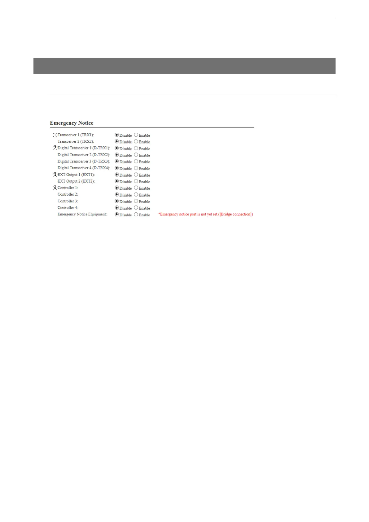
M Emergency Notice
Select the port to use as the emergency notice output.
q Transceiver 1 (TRX1)
Transceiver 2 (TRX2) …… If you select “Enable,” the emergency notice is sent to the port ([TRX1]/
[TRX2]). (Default: Disable)
w Digital Transceiver 1 (D-TRX1) –
Digital Transceiver 4 (D-TRX4)
…………………………… If you select “Enable,” the emergency notice is sent to the port ([D-TRX1] to
[D-TRX4]). (Default: Disable)
• One CT-24 is necessary for each D-TRX port to notice.
e EXT I/O 1 (EXT1)
EXT Output 2 (EXT2) …… If you select “Enable,” the emergency notice is sent to the connected
transceiver or external device. (Default: Disable)
r Controller 1 –
Controller 4 ……………… If you select “Enable,” the emergency notice is sent to the IP1000C.
(Default: Disable)
t Emergency Notice Equipment If you select “Enable,” the emergency notice is sent to the specified Bridge
connect destination. (Default: Disable)
• Select “Emergency” in [Input Connection Port] on the [EXT Input 1 (EXT1)]/
[EXT Input 2 (EXT2)] (Or EXT I/O1/2) screen.
9. [Expansion] Menu (continued)
[Expansion]–[Abnormal Condition Monitoring]
t