2
BRIDGE MODE APPLICATION
2-6
1
2
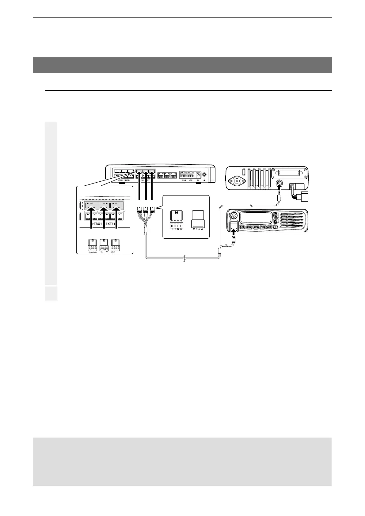
VE-PG3 (Rear view)
Icom’s transceiver
(IC-F5060/IC-F6060 series)
(Rear view)
(Front view)
To the external speaker jack
To the microphone connector
LINE2
LINE1
PHONE
• The [TRX1] and [TRX2] ports (upper slots) accept the OPC-2275 connectors,
however, follow the example to correctly connect the transceiver to ONLY the [TRX1] on the VE-PG3.
ABC
Be sure to insert the
connectors top side up.
Bottom
To p
A
1234
OPC-2275
AABC
To [TRX1] (Upper slots)
2. Operation in the Unicast mode (continued)
NOTE:
• Verify that both the radio and the VE-PG3 are turned OFF when connecting or disconnecting the transceiver.
• Keep the radio away from a PC, AC adaptor and other electronic equipment. The noise emitted from those equipment may
interfere with the radio.
• When operating the radio, do not transmit near the IP telephone.
2. Connection
Set the transceiver channel, volume level, TX output power, and other necessary settings, before connecting to the
VE-PG3.
When all the connections are finished, turn ON the transceiver and VE-PG3’s power.
Connect the VE-PG3 and the transceiver, using the appropriate optional cable.
• Verify that both the VE-PG3 and the transceiver are turned OFF when connecting the cable.