2
BRIDGE MODE APPLICATION
2-12
4. Operating in the NXDN Conventional mode (continued)
Menu Item Setting Screen Setting Item Item Name Value
Bridge
Connection
Bridge Connection Point Bridge Connection Point Port Type Transceiver 1(TRX1)
(TRX1) Connection IP Address 192.168.0.2 (VE-PG3’s IP address)
Connection Port Number 21502 (VE-PG3's unused port)
Voice Codec AMBE+2
(D-TRX1) Port Type Digital Transceiver 1 (D-TRX1)
SelCall in Bridge
Connection
Enable
Voice Codec AMBE+2
(D-TRX2) Port Type Digital Transceiver 2 (D-TRX2)
SelCall in Bridge
Connection
Enable
Voice Codec AMBE+2
List of Bridge Connection
Point Entries
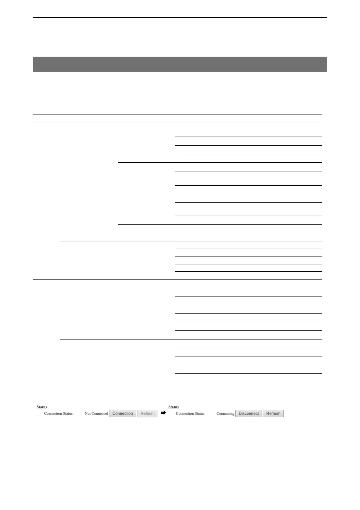
Connection Status During transmit
SelCall in Bridge Connection SelCall in Bridge Connection Radio B1 Destination ID 1/192.168.0.2 /21504
Radio B2 Destination ID 2/192.168.0.2 /21504
Radio C1 Destination ID 3/192.168.0.2 /21506
Radio C2 Destination ID 4/192.168.0.2 /21506
Radio A1 Destination ID 8/192.168.0.2 /21500
Port Settings
Transceiver 1 (TRX1)
Transceiver Model Transceiver Model IC-F5060/F6060
Digital Transceiver 1 (D-TRX1)
Transceiver Model Mode: NXDN Conventional
Repeater Address UC-FR5000’s IP address
TCP Port Number Connection: Receive port No. (ex. 41200)
UDP Port Number Data: Receive port No. (ex. 41220)
Connect Key UR-FR5000’s key code
Unit ID Unit ID (ex. 10)
Digital Transceiver 2 (D-TRX2)
Transceiver Model Mode: NXDN Conventional
Repeater Address UC-FR5000’s IP address
TCP Port Number Connection: Receive port No. (ex. 41200)
UDP Port Number Data: Receive port No. (ex. 41220)
Connect Key UC-FR5000’s key code
Unit ID Unit ID (ex. 20)
2. VE-PG3 configuration
Access the VE-PG3 setting screen, and set the items as shown below.
• After the configuration, click [Connection] to connect to the network.