Datasheet 109
PCH Pin States
NOTE:
1. These signals can be configured as outputs in GPIO mode.
2. This signal is sampled as a functional strap during Reset. Refer to Functional straps
definition table for usage.
3. External termination is also required for JTAG enabling.
4. Not all signals or pin functionalities may be available on a given SKU. See Section 1.3 and
Chapter 2 for details.
Miscellaneous Signals
INTVRMEN
2
RTC External Pull-up High High High
RTCRST# RTC External RC Circuit High High High
SRTCRST# RTC External RC Circuit High High High
Digital Display Interface
DDP[B:C:D]_HPD Core External Pull-down Driven Off Off
SDVO_INTP,
SDVO_INTN
Core SDVO controller device Driven Off Off
SDVO_TVCLKINP,
SDVO_TVCLKINN
Core SDVO controller device Driven Off Off
SDVO_STALLP,
SDVO_STALLN
Core SDVO controller device Driven Off Off
Intel
®
Flexible Display Interface
FDI_RXP[7:0],
FDI_RXN[7:0]
Core Processor Driven Off Off
Clock Interface
CLKIN_SATA_N,
CLKIN_SATA_P
Core External pull-down Low Off Off
CLKIN_DOT_96P,
CLKIN_DOT_96N
Core External pull-down Low Off Off
CLKIN_DMI_P,
CLKIN_DMI_N
Core External pull-down Low Off Off
CLKIN_PCILOOPBACK Core Clock Generator Running Off Off
PCIECLKRQ[7:5]#/
GPIO[46:44]
1
Suspend External Pull-up Driven Driven Driven
PCIECLKRQ2#/GPIO20
1
Core External Pull-up Driven Off Off
REFCLK14IN Core External Pull-down Low Off Off
XTAL25_IN Core Clock Generator High-Z High-Z High-Z
Intel
®
High Definition Audio Interface
SPI Interface
SPI_MISO ASW Internal Pull-up Driven Driven Driven
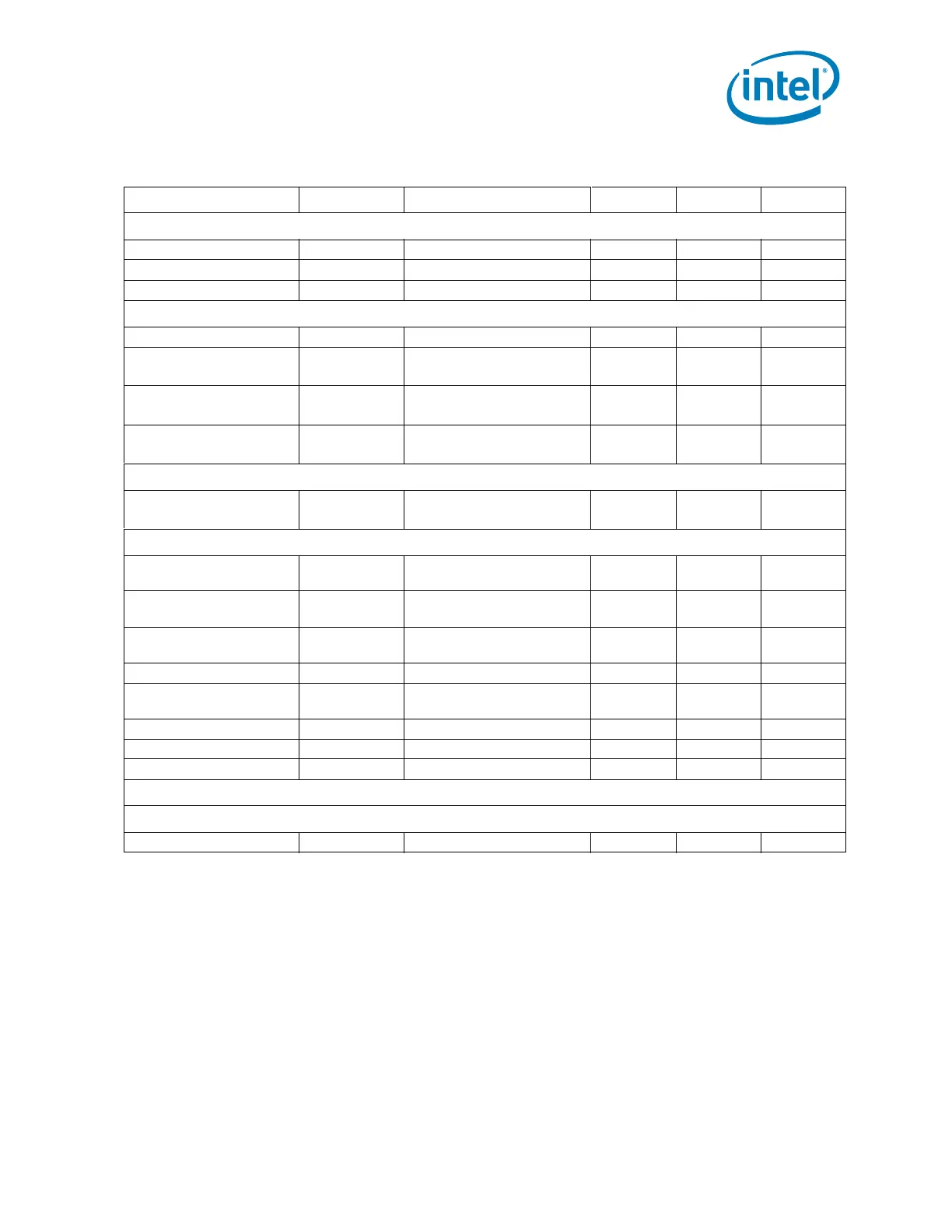
Table 3-4. Power Plane for Input Signals for Desktop Configurations (Sheet 3 of 3)
Signal Name Power Well Driver During Reset S0/S1 S3 S4/S5
 Loading...
