Functional Description
132 Datasheet
5.4.1.5 SYNC
Valid values for the SYNC field are shown in Table 5-11.
NOTES:
1. All other combinations are RESERVED.
2. If the LPC controller receives any SYNC returned from the device other than short (0101),
long wait (0110), or ready (0000) when running a FWH cycle, indeterminate results may
occur. A FWH device is not allowed to assert an Error SYNC.
5.4.1.6 SYNC Time-Out
There are several error cases that can occur on the LPC interface. The PCH responds as
defined in section 4.2.1.9 of the Low Pin Count Interface Specification, Revision 1.1 to
the stimuli described therein. There may be other peripheral failure conditions;
however, these are not handled by the PCH.
5.4.1.7 SYNC Error Indication
The PCH responds as defined in section 4.2.1.10 of the Low Pin Count Interface
Specification, Revision 1.1.
Upon recognizing the SYNC field indicating an error, the PCH treats this as a SERR by
reporting this into the Device 31 Error Reporting Logic.
5.4.1.8 LFRAME# Usage
The PCH follows the usage of LFRAME# as defined in the Low Pin Count Interface
Specification, Revision 1.1.
The PCH performs an abort for the following cases (possible failure cases):
• The PCH starts a Memory, I/O, or DMA cycle, but no device drives a valid SYNC
after four consecutive clocks.
• The PCH starts a Memory, I/O, or DMA cycle, and the peripheral drives an invalid
SYNC pattern.
• A peripheral drives an illegal address when performing bus master cycles.
• A peripheral drives an invalid value.
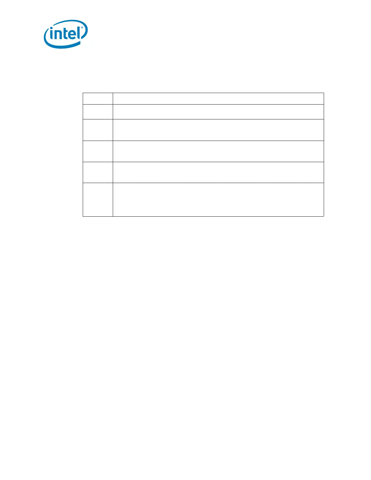
Table 5-11. SYNC Bit Definition
Bits[3:0] Indication
0000
Ready: SYNC achieved with no error. For DMA transfers, this also indicates DMA
request deassertion and no more transfers desired for that channel.
0101
Short Wait: Part indicating wait-states. For bus master cycles, the PCH does not
use this encoding. Instead, the PCH uses the Long Wait encoding (see next encoding
below).
0110
Long Wait: Part indicating wait-states, and many wait-states will be added. This
encoding driven by the PCH for bus master cycles, rather than the Short Wait
(0101).
1001
Ready More (Used only by peripheral for DMA cycle): SYNC achieved with no
error and more DMA transfers desired to continue after this transfer. This value is
valid only on DMA transfers and is not allowed for any other type of cycle.
1010
Error: Sync achieved with error. This is generally used to replace the SERR# or
IOCHK# signal on the PCI/ISA bus. It indicates that the data is to be transferred,
but there is a serious error in this transfer. For DMA transfers, this not only indicates
an error, but also indicates DMA request deassertion and no more transfers desired
for that channel.
 Loading...
