Datasheet 189
Functional Description
The idle field is enforced by the hardware and is at least 2 bit times long. The hardware
will not clear the Busy and Go bits until this idle time is met. Supporting the idle time in
hardware prevents time-based counting in BIOS as the hardware is immediately ready
for the next serial code when the Go bit is cleared. Note that the idle state is
represented as a high-Z condition on the pin. If the last transmitted bit is a 1, returning
to the idle state will result in a final 0-1 transition on the output Manchester data. Two
full bit times of idle correspond to a count of 4 time intervals (the width of the time
interval is controlled by the DRS field).
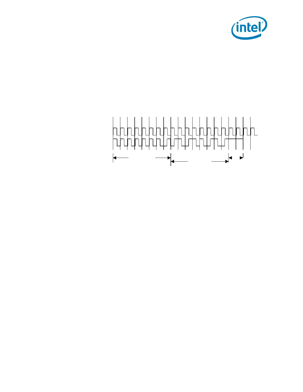
The following waveform shows a 1-byte serial write with a data byte of 5Ah. The
internal clock and bit position are for reference purposes only. The Manchester D is the
resultant data generated and serialized onto the GPIO. Since the buffer is operating in
open-drain mode the transitions are from high-Z to 0 and back.
5.16 SATA Host Controller (D31:F2, F5)
The SATA function in the PCH has three modes of operation to support different
operating system conditions. In the case of Native IDE enabled operating systems, the
PCH uses two controllers to enable all six ports of the bus. The first controller
(Device 31: Function 2) supports ports 0 – 3 and the second controller (Device 31:
Function 5) supports ports 4 and 5. When using a legacy operating system, only one
controller (Device 31: Function 2) is available that supports ports 0 – 3. In AHCI or
RAID mode, only one controller (Device 31: Function 2) is utilized enabling all six ports
and the second controller (Device 31: Function 5) shall be disabled.
The MAP register, Section 15.1.25, provides the ability to share PCI functions. When
sharing is enabled, all decode of I/O is done through the SATA registers. Device 31,
Function 1 (IDE controller) is hidden by software writing to the Function Disable
Register (D31, F0, Offset F2h, bit 1), and its configuration registers are not used.
The PCH SATA controllers feature six sets of interface signals (ports) that can be
independently enabled or disabled (they cannot be tri-stated or driven low). Each
interface is supported by an independent DMA controller.
The PCH SATA controllers interact with an attached mass storage device through a
register interface that is equivalent to that presented by a traditional IDE host adapter.
The host software follows existing standards and conventions when accessing the
register interface and follows standard command protocol conventions.
Note: SATA interface transfer rates are independent of UDMA mode settings. SATA interface
transfer rates will operate at the bus’s maximum speed, regardless of the UDMA mode
reported by the SATA device or the system BIOS.
Internal Clock
Manchester D
8-bit sync field
(1111_1110)
Bit 7 0123456
5A data byte
2 clk
idle