Datasheet 67
Signal Description
2.9 Processor Interface
2.10 SMBus Interface
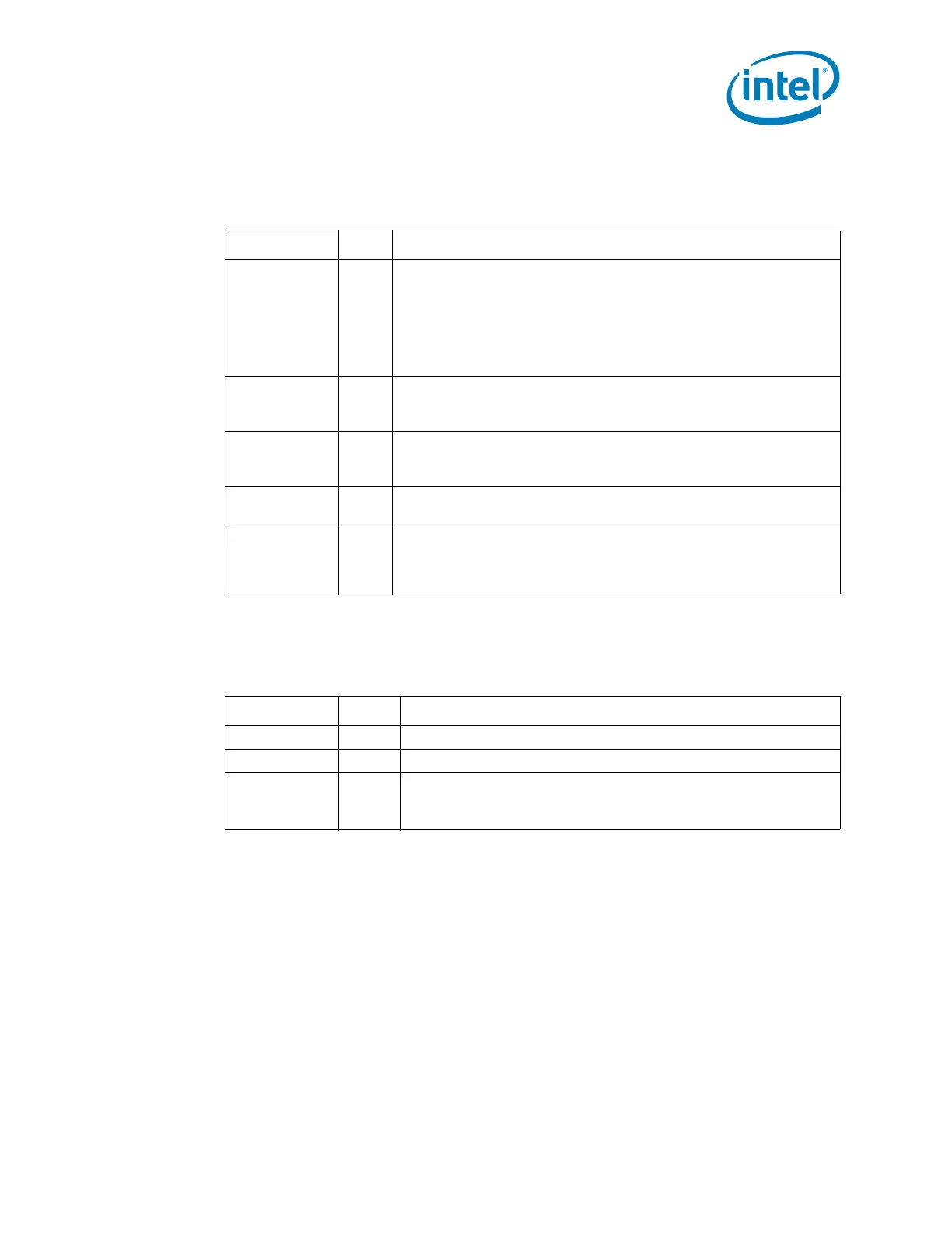
Table 2-9. Processor Interface Signals
Name Type Description
RCIN# I
Keyboard Controller Reset Processor: The keyboard controller
can generate INIT# to the processor. This saves the external OR gate
with the PCH’s other sources of INIT#. When the PCH detects the
assertion of this signal, INIT# is generated using a VLW message to
the processor.
NOTE: The PCH will ignore RCIN# assertion during transitions to the
S3, S4, and S5 states.
A20GATE I
A20 Gate: A20GATE is from the keyboard controller. The signal acts
as an alternative method to force the A20M# VLW message to the
processor active.
PROCPWRGD O
Processor Power Good: This signal should be connected to the
processor’s UNCOREPWRGOOD input to indicate when the processor
power is valid.
PMSYNCH O
Power Management Sync: Provides state information from the PCH
to the processor
THRMTRIP# I
Thermal Trip: When low, this signal indicates that a thermal trip
from the processor occurred, and the PCH will immediately transition
to a S5 state. The PCH will not wait for the processor stop grant cycle
since the processor has overheated.
Table 2-10. SM Bus Interface Signals
Name Type Description
SMBDATA I/OD SMBus Data: External pull-up resistor is required.
SMBCLK I/OD SMBus Clock: External pull-up resistor is required.
SMBALERT# /
GPIO11
I
SMBus Alert: This signal is used to wake the system or generate
SMI#.
This signal may be used as GPIO11.