Datasheet 225
Functional Description
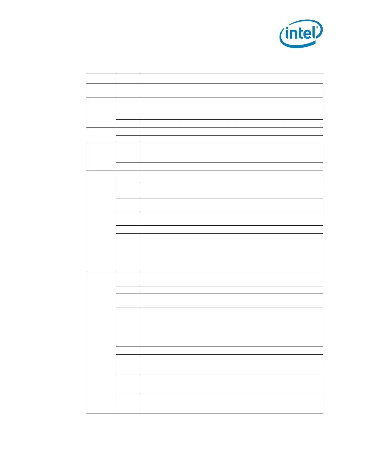
Table 5-51. Data Values for Slave Read Registers (Sheet 1 of 2)
Register Bits Description
07:0
Reserved for capabilities indication. Should always return 00h. Future
chips may return another value to indicate different capabilities.
1
2:0
System Power State
000 = S0 001 = S1 010 = Reserved 011 = S3
100 = S4 101 = S5 110 = Reserved 111 = Reserved
7:3 Reserved
2
3:0 Reserved
7:4 Reserved
3
5:0
Watchdog Timer current value Note that Watchdog Timer has 10 bits,
but this field is only 6 bits. If the current value is greater than 3Fh, the
PCH will always report 3Fh in this field.
7:6 Reserved
4
0
1 = The Intruder Detect (INTRD_DET) bit is set. This indicates that the
system cover has probably been opened.
1
1 = BTI Temperature Event occurred. This bit will be set if the PCH’s
THRM# input signal is active. Else this bit will read “0.”
2
DOA Processor Status. This bit will be 1 to indicate that the processor is
dead
3
1 = SECOND_TO_STS bit set. This bit will be set after the second time-
out (SECOND_TO_STS bit) of the Watchdog Timer occurs.
6:4 Reserved. Will always be 0, but software should ignore.
7
Reflects the value of the GPIO[11]/SMBALERT# pin (and is dependent
upon the value of the GPI_INV[11] bit. If the GPI_INV[11] bit is 1, then
the value in this bit equals the level of the GPI[11]/SMBALERT# pin
(high = 1, low = 0).
If the GPI_INV[11] bit is 0, then the value of this bit will equal the inverse
of the level of the GPIO[11]/SMBALERT# pin (high = 0, low = 1).
5
0
FWH bad bit. This bit will be 1 to indicate that the FWH read returned
FFh, which indicates that it is probably blank.
1 Reserved
2
SYS_PWROK Failure Status: This bit will be 1 if the SYSPWR_FLR bit in
the GEN_PMCON_2 register is set.
3
INIT3_3V# due to receiving Shutdown message: This event is
visible from the reception of the shutdown message until a platform reset
is done if the Shutdown Policy Select bit (SPS) is configured to drive
INIT3_3V#. When the SPS bit is configured to generate PLTRST# based
on shutdown, this register bit will always return 0.
Events on signal will not create a event message
4 Reserved
5
POWER_OK_BAD: Indicates the failure core power well ramp during
boot/resume. This bit will be active if the SLP_S3# pin is deasserted and
PWROK pin is not asserted.
6
Thermal Trip: This bit will shadow the state of processor Thermal Trip
status bit (CTS) (16.2.1.2, GEN_PMCON_2, bit 3). Events on signal will
not create a event message
7
Reserved: Default value is “X”
NOTE: Software should not expect a consistent value when this bit is read
through SMBUS/SMLink
 Loading...
