Datasheet 503
LPC Interface Bridge Registers (D31:F0)
13.7 Processor Interface Registers
Table 13-8 is the register address map for the processor interface registers.
13.7.1 NMI_SC—NMI Status and Control Register
I/O Address: 61h Attribute: R/W, RO
Default Value: 00h Size: 8-bit
Lockable: No Power Well: Core
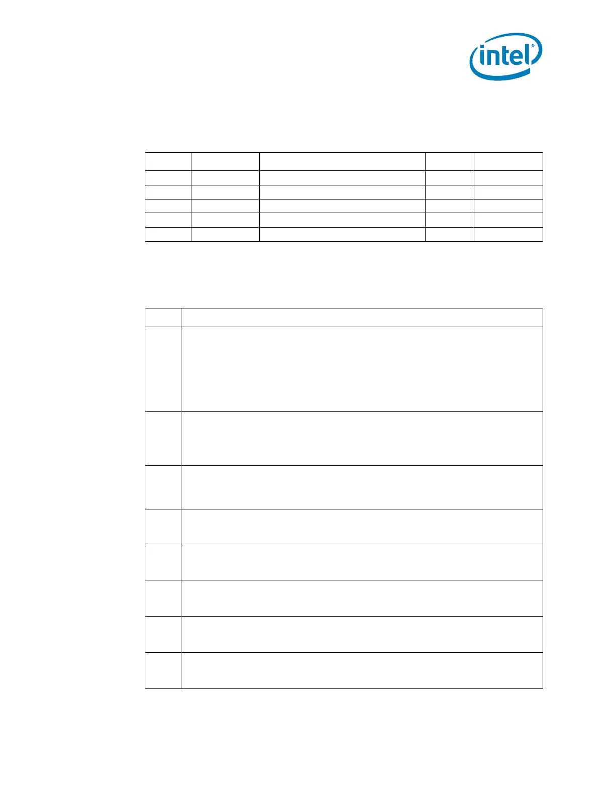
Table 13-8. Processor Interface PCI Register Address Map
Offset Mnemonic Register Name Default Type
61h NMI_SC NMI Status and Control 00h R/W, RO
70h NMI_EN NMI Enable 80h R/W (special)
92h PORT92 Fast A20 and Init 00h R/W
F0h COPROC_ERR Coprocessor Error 00h WO
CF9h RST_CNT Reset Control 00h R/W
Bit Description
7
SERR# NMI Source Status (SERR#_NMI_STS) — RO.
1 = Bit is set if a PCI agent detected a system error and pulses the PCI SERR# line and
if bit 2 (PCI_SERR_EN) is cleared. This interrupt source is enabled by setting bit 2
to 0. To reset the interrupt, set bit 2 to 1 and then set it to 0. When writing to port
61h, this bit must be 0.
NOTE: This bit is set by any of the PCH internal sources of SERR; this includes SERR
assertions forwarded from the secondary PCI bus, errors on a PCI Express*
port, or other internal functions that generate SERR#.
6
IOCHK# NMI Source Status (IOCHK_NMI_STS) — RO.
1 = Bit is set if an LPC agent (using SERIRQ) asserted IOCHK# and if bit 3
(IOCHK_NMI_EN) is cleared. This interrupt source is enabled by setting bit 3 to 0.
To reset the interrupt, set bit 3 to 1 and then set it to 0. When writing to port 61h,
this bit must be a 0.
5
Timer Counter 2 OUT Status (TMR2_OUT_STS) — RO. This bit reflects the current
state of the 8254 counter 2 output. Counter 2 must be programmed following any PCI
reset for this bit to have a determinate value. When writing to port 61h, this bit must
be a 0.
4
Refresh Cycle Toggle (REF_TOGGLE) — RO. This signal toggles from either 0 to 1 or
1 to 0 at a rate that is equivalent to when refresh cycles would occur. When writing to
port 61h, this bit must be a 0.
3
IOCHK# NMI Enable (IOCHK_NMI_EN) — R/W.
0 = Enabled.
1 = Disabled and cleared.
2
PCI SERR# Enable (PCI_SERR_EN) — R/W.
0 = SERR# NMIs are enabled.
1 = SERR# NMIs are disabled and cleared.
1
Speaker Data Enable (SPKR_DAT_EN) — R/W.
0 = SPKR output is a 0.
1 = SPKR output is equivalent to the Counter 2 OUT signal value.
0
Timer Counter 2 Enable (TIM_CNT2_EN) — R/W.
0 = Disable
1 = Enable