Datasheet 327
Electrical Characteristics
NOTES:
1. A device will timeout when any clock low exceeds this value.
2. t137 is the cumulative time a slave device is allowed to extend the clock cycles in one
message from the initial start to stop. If a slave device exceeds this time, it is expected to
release both its clock and data lines and reset itself.
3. t138 is the cumulative time a master device is allowed to extend its clock cycles within
each byte of a message as defined from start-to-ack, ack-to-ack or ack-to-stop.
4. t134 has a minimum timing for I
2
C of 0 ns, while the minimum timing for SMBus/SMLINK
is 300 ns.
5. Timings with the SMLFM designator apply only to SMLink0 and only when SMLink0 is
operating in Fast Mode.
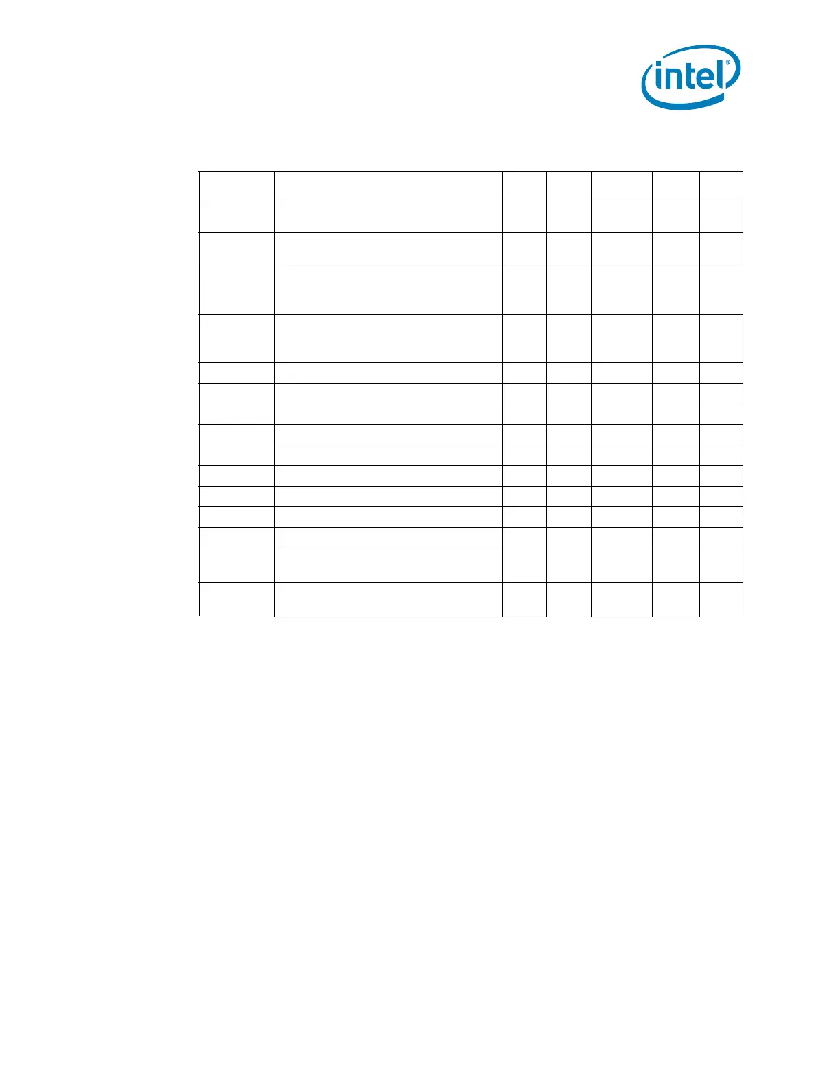
Table 8-28. SMBus and SMLink Timing
Sym Parameter Min Max Units Notes Fig
t130
Bus Free Time Between Stop and Start
Condition
4.7 — µs 8-20
t130SMLFM
Bus Free Time Between Stop and Start
Condition
1.3 — µs 58-20
t131
Hold Time after (repeated) Start
Condition. After this period, the first
clock is generated.
4.0 — µs 8-20
t131SMLFM
Hold Time after (repeated) Start
Condition. After this period, the first
clock is generated.
0.6 — µs 58-20
t132 Repeated Start Condition Setup Time 4.7 — µs 8-20
t132SMLFM Repeated Start Condition Setup Time 0.6 — µs 58-20
t133 Stop Condition Setup Time 4.0 — µs 8-20
t133SMLFM Stop Condition Setup Time 0.6 — µs 58-20
t134 Data Hold Time 0 — ns 48-20
t134SMLFM Data Hold Time 0 — ns 4, 5 8-20
t135 Data Setup Time 250 — ns 8-20
t135SMLFM Data Setup Time 100 — ns 58-20
t136 Device Time Out 25 35 ms 1
t137
Cumulative Clock Low Extend Time
(slave device)
—25 ms 28-21
t138
Cumulative Clock Low Extend Time
(master device)
—10 ms 38-21