Electrical Characteristics
330 Datasheet
NOTE:
1. Typical clock frequency driven by the PCH is 50 MHz.
2. When using 50 MHz mode ensure target flash component can meet t188c and t189c
specifications. Measurement should be taken at a point as close as possible to the package
pin.
3. Measurement point for low time and high time is taken at 0.5(VccSPI).
NOTES:
1. Measured from (CL_Vref – 50 mV to CL_Vref + 50 mV) at the receiving device side. No
test load is required for this measurement as the receiving device fulfills this purpose.
2. CL_Vref = 0.12*(VccSus3_3).
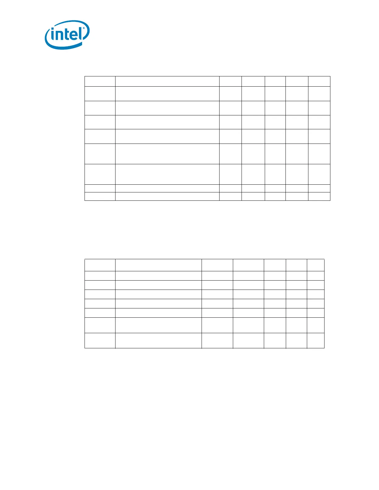
Table 8-34. SPI Timings (50 MHz)
Sym Parameter Min Max Units Notes Fig
t180c
Serial Clock Frequency - 50-MHz
Operation
46.99 53.40 MHz 1
t183c
Tco of SPI_MOSI with respect to serial
clock falling edge at the host
-3 3 ns 8-22
t184c
Setup of SPI_MISO with respect to
serial clock falling edge at the host
8—ns 8-22
t185c
Hold of SPI_MISO with respect to serial
clock falling edge at the host
0—ns 8-22
t186c
Setup of SPI_CS[1:0]# assertion with
respect to serial clock rising edge at the
host
30 — ns 8-22
t187c
Hold of SPI_CS[1:0]# assertion with
respect to serial clock rising edge at the
host
30 — ns 8-22
t188c SPI_CLK High time 7.1 — ns 2, 3 8-22
t189c SPI_CLK Low time 11.17 — ns 2, 3 8-22
Table 8-35. Controller Link Receive Timings
Sym Parameter Min Max Units Notes Fig
t190 Single bit time 13 — ns 8-32
t191 Single clock period 15 — ns 8-32
t192 Rise time/Fall time 0.11 3.5 V/ns 1 8-33
t193 Setup time before CL_CLK1 0.9 — ns 8-32
t194 Hold time after CL_CLK1 0.9 — ns 8-32
V
IL_AC
Input low voltage (AC)
CL_Vref -
0.08
V2
V
IH_AC
Input high voltage (AC)
CL_Vref
+0.08
V2