Signal Description
68 Datasheet
2.11 System Management Interface
2.12 Real Time Clock Interface
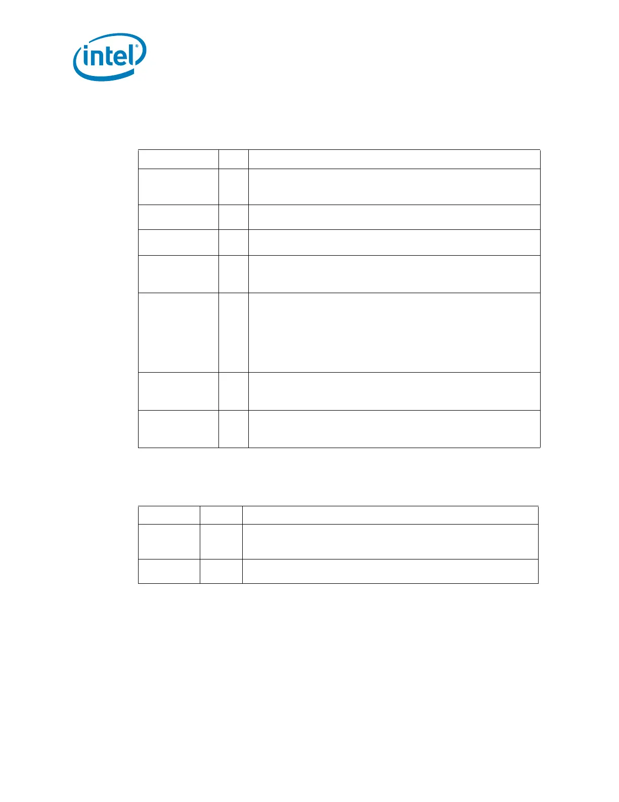
Table 2-11. System Management Interface Signals
Name Type Description
INTRUDER# I
Intruder Detect: This signal can be set to disable the system if box
detected open. This signal’s status is readable, so it can be used like a
GPI if the Intruder Detection is not needed.
SML0DATA I/OD
System Management Link 0 Data: SMBus link to external PHY.
External pull-up is required.
SML0CLK I/OD
System Management Link 0 Clock: SMBus link to external PHY.
External pull-up is required.
SML0ALERT# /
GPIO60
O OD
SMLink Alert 0: Output of the integrated LAN controller to external
PHY. External pull-up resistor is required.
This signal can instead be used as GPIO60.
SML1ALERT# /
PCHHOT# /
GPIO74
O OD
SMLink Alert 1: Alert for the ME SMBus controller to optional
Embedded Controller or BMC. External pull-up resistor is required.
This signal can instead be used as PCHHOT# or GPIO74
NOTE: A soft-strap determines the native function SML1ALERT# or
PCHHOT# usage. When soft-strap is 0, function is
SML1ALERT#, when soft-strap is 1, function is PCHHOT#.
SML1CLK /
GPIO58
I/OD
System Management Link 1 Clock: SMBus link to optional
Embedded Controller or BMC. External pull-up resistor is required.
This signal can instead be used as GPIO58
SML1DATA /
GPIO75
I/OD
System Management Link 1 Data: SMBus link to optional
Embedded Controller or BMC. External pull-up resistor is required.
This signal can instead be used as GPIO75
Table 2-12. Real Time Clock Interface
Name Type Description
RTCX1 Special
Crystal Input 1: This signal is connected to the 32.768 kHz crystal. If
no external crystal is used, then RTCX1 can be driven with the desired
clock rate.
RTCX2 Special
Crystal Input 2: This signal is connected to the 32.768 kHz crystal. If
no external crystal is used, then RTCX2 should be left floating.