Datasheet 197
Functional Description
to the actual bit stream transmission. The Host will drive SLOAD low for at least 5
SCLOCK then only start the bit stream by driving the SLOAD to high. SLOAD will be
driven high for 1 SCLOCK follow by vendor specific pattern that is default to “0000” if
software has yet to program the value. A total of 21-bit stream from 7 ports (Port0,
Port1, Port2, Port3, Port4 Port5 and Port6) of 3-bit per port LED message will be
transmitted on SDATAOUT0 pin after the SLOAD is driven high for 1 SCLOCK. Only 3
ports (Port4, Port5 and Port6) of 9 bit total LED message follow by 12 bits of tri-state
value will be transmitted out on SDATAOUT1 pin.
All the default LED message values will be high prior to software setting them, except
the Activity LED message that is configured to be hardware driven that will be
generated based on the activity from the respective port. All the LED message values
will be driven to ‘1’ for the port that is unimplemented as indicated in the Port
Implemented register regardless of the software programmed value through the
message buffer.
There are 2 different ways of resetting the PCH’s SGPIO interface, asynchronous reset
and synchronous reset. Asynchronous reset is caused by platform reset to cause the
SGPIO interface to be tri-state asynchronously. Synchronous reset is caused by setting
the CTL.RESET bit, clearing the GHC.AE bit or HBA reset, where Host Controller will
complete the existing full bit stream transmission then only tri-state all the SGPIO pins.
After the reset, both synchronous and asynchronous, the SGPIO pins will stay tri-
stated.
Note: The PCH Host Controller does not ensure that it will cause the target SGPIO device or
controller to be reset. Software is responsible to keep the PCH SGPIO interface in tri-
state for 2 second to cause a reset on the target of the SGPIO interface.
5.16.12.2 Message Format
Messages shall be constructed with a one DWord header that describes the message to
be sent followed by the actual message contents. The first DWord shall be constructed
as follows:
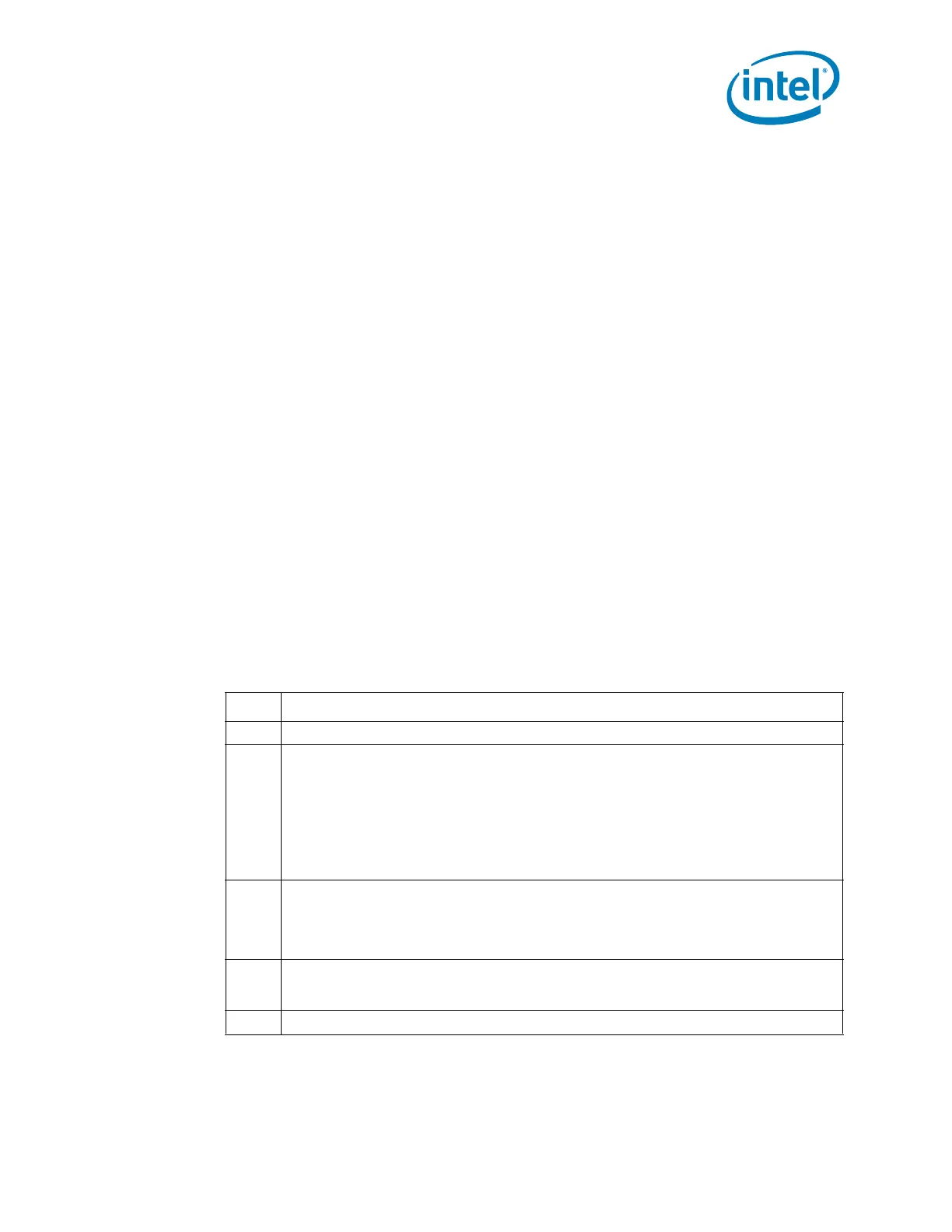
Bit Description
31:28 Reserved
27:24
Message Type (MTYPE): Specifies the type of the message.
The message types are:
0h = LED
1h = SAF-TE
2h = SES-2
3h = SGPIO (register based interface)
All other values reserved
23:16
Data Size (DSIZE): Specifies the data size in bytes. If the message (enclosure
services command) has a data buffer that is associated with it that is transferred, the
size of that data buffer is specified in this field. If there is no separate data buffer, this
field shall have a value of ‘0’. The data directly follows the message in the message
buffer. For the PCH, this value should always be ‘0’.
15:8
Message Size (MSIZE): Specifies the size of the message in bytes. The message size
does not include the one DWord header. A value of ‘0’ is invalid. For the PCH, the
message size is always 4 bytes.
7:0 Reserved