Datasheet 137
Functional Description
5.6 LPC DMA
DMA on LPC is handled through the use of the LDRQ# lines from peripherals and
special encodings on LAD[3:0] from the host. Single, Demand, Verify, and Increment
modes are supported on the LPC interface. Channels 0–3 are 8-bit channels. Channels
5–7 are 16-bit channels. Channel 4 is reserved as a generic bus master request.
5.6.1 Asserting DMA Requests
Peripherals that need DMA service encode their requested channel number on the
LDRQ# signal. To simplify the protocol, each peripheral on the LPC I/F has its own
dedicated LDRQ# signal (they may not be shared between two separate peripherals).
The PCH has two LDRQ# inputs, allowing at least two devices to support DMA or bus
mastering.
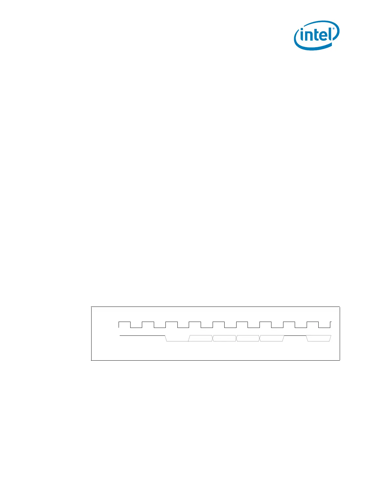
LDRQ# is synchronous with LCLK (PCI clock). As shown in Figure 5-4, the peripheral
uses the following serial encoding sequence:
• Peripheral starts the sequence by asserting LDRQ# low (start bit). LDRQ# is high
during idle conditions.
• The next three bits contain the encoded DMA channel number (MSB first).
• The next bit (ACT) indicates whether the request for the indicated DMA channel is
active or inactive. The ACT bit is 1 (high) to indicate if it is active and 0 (low) if it is
inactive. The case where ACT is low is rare, and is only used to indicate that a
previous request for that channel is being abandoned.
• After the active/inactive indication, the LDRQ# signal must go high for at least one
clock. After that one clock, LDRQ# signal can be brought low to the next encoding
sequence.
If another DMA channel also needs to request a transfer, another sequence can be sent
on LDRQ#. For example, if an encoded request is sent for Channel 2, and then Channel
3 needs a transfer before the cycle for Channel 2 is run on the interface, the peripheral
can send the encoded request for Channel 3. This allows multiple DMA agents behind
an I/O device to request use of the LPC interface, and the I/O device does not need to
self-arbitrate before sending the message.
5.6.2 Abandoning DMA Requests
DMA Requests can be deasserted in two fashions: on error conditions by sending an
LDRQ# message with the ‘ACT’ bit set to 0, or normally through a SYNC field during the
DMA transfer. This section describes boundary conditions where the DMA request needs
to be removed prior to a data transfer.
There may be some special cases where the peripheral desires to abandon a DMA
transfer. The most likely case of this occurring is due to a floppy disk controller which
has overrun or underrun its FIFO, or software stopping a device prematurely.
Figure 5-4. DMA Request Assertion through LDRQ#
Start MSB LSB ACT Start
LCLK
LDRQ#