Functional Description
252 Datasheet
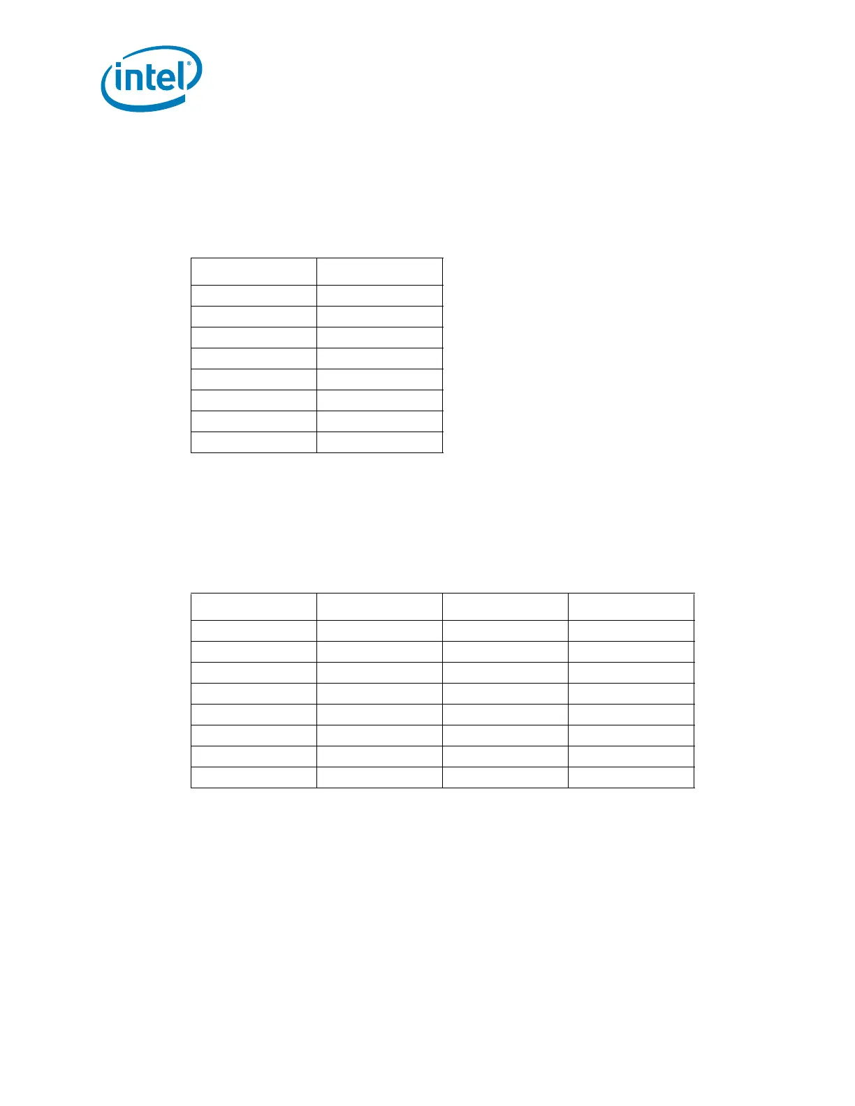
5.24.7 SPI Flash Device Recommended Pinout
Table 5-59 contains the recommended serial flash device pin-out for an 8-pin device.
Use of the recommended pin-out on an 8-pin device reduces complexities involved with
designing the serial flash device onto a motherboard and allows for support of a
common footprint usage model (refer to Section 5.24.8.1).
Although an 8-pin device is preferred over a 16-pin device due to footprint
compatibility, the following table contains the recommended serial flash device pin-out
for a 16-pin SOIC.
5.24.8 Serial Flash Device Package
5.24.8.1 Common Footprint Usage Model
In order to minimize platform motherboard redesign and to enable platform Bill of
Material (BOM) selectability, many PC System OEMs design their motherboard with a
single common footprint. This common footprint allows population of a soldered down
device or a socket that accepts a leadless device. This enables the board manufacturer
to support, using selection of the appropriate BOM, either of these solutions on the
same system without requiring any board redesign.
Table 5-59. Recommended Pinout for 8-Pin Serial Flash Device
Pin # Signal
1Chips Select
2 Data Output
3 Write Protect
4Ground
5 Data Input
6Serial Clock
7Hold / Reset
8 Supply Voltage
Table 5-60. Recommended Pinout for 16-Pin Serial Flash Device
Pin # Signal Pin # Signal
1 Hold / Reset 9 Write Protect
2 Supply Voltage 10 Ground
3 No Connect 11 No Connect
4 No Connect 12 No Connect
5 No Connect 13 No Connect
6 No Connect 14 No Connect
7 Chip Select 15 Serial Data In
8 Serial Data Out 16 Serial Clock