Register and Memory Mapping
354 Datasheet
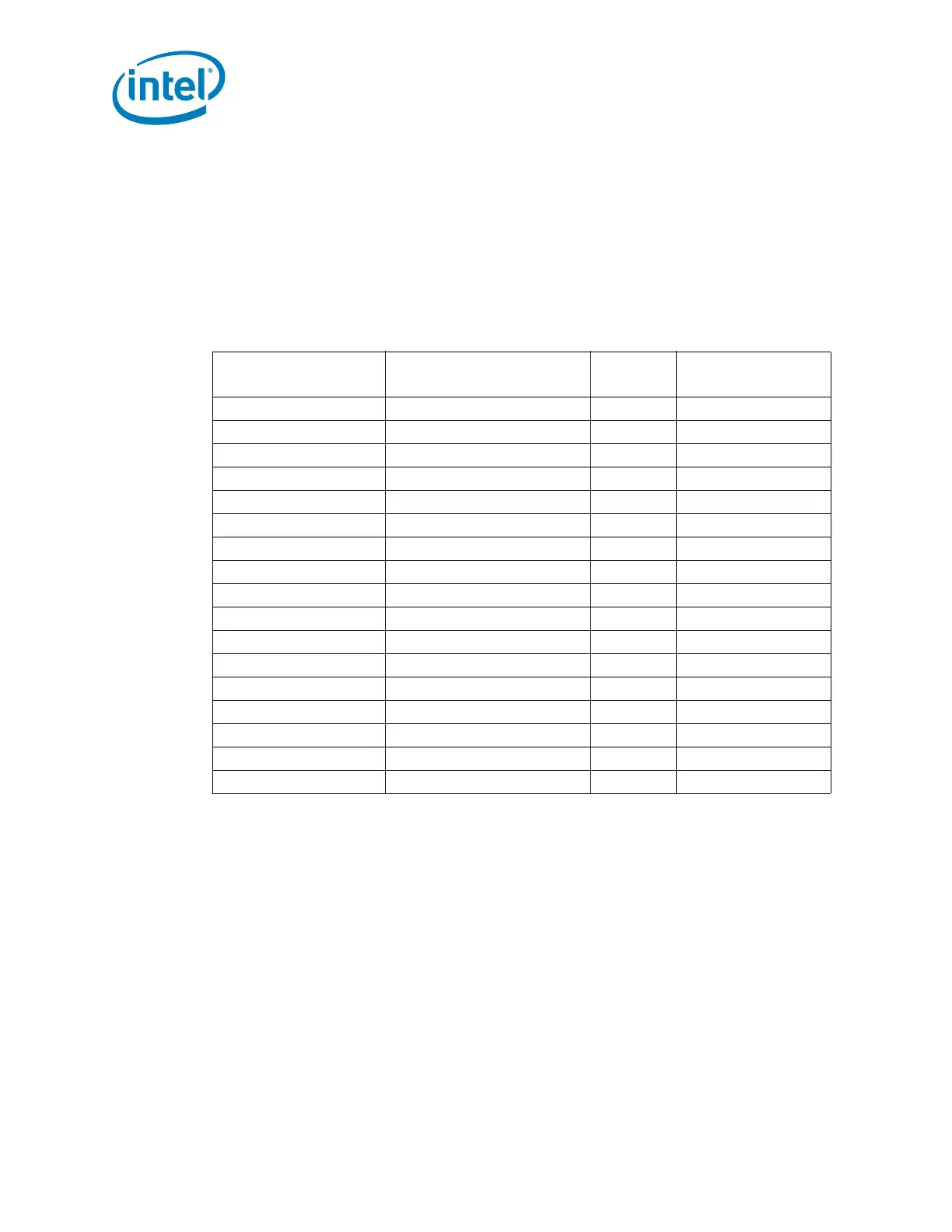
9.3.2 Variable I/O Decode Ranges
Table 9-3 shows the Variable I/O Decode Ranges. They are set using Base Address
Registers (BARs) or other configuration bits in the various PCI configuration spaces.
The PNP software (PCI or ACPI) can use their configuration mechanisms to set and
adjust these values.
Warning: The Variable I/O Ranges should not be set to conflict with the Fixed I/O Ranges.
Unpredictable results if the configuration software allows conflicts to occur. The PCH
does not perform any checks for conflicts.
NOTE:
1. Decode range size determined by D31:F0:ADh:bits 5:4
Table 9-3. Variable I/O Decode Ranges
Range Name Mappable
Size
(Bytes)
Target
ACPI Anywhere in 64 KB I/O Space 64 Power Management
IDE Bus Master Anywhere in 64 KB I/O Space 16 IDE Unit
Native IDE Command Anywhere in 64 KB I/O Space 8 IDE Unit
Native IDE Control Anywhere in 64 KB I/O Space 4 IDE Unit
SMBus Anywhere in 64 KB I/O Space 32 SMB Unit
TCO 96 Bytes above ACPI Base 32 TCO Unit
GPIO Anywhere in 64 KB I/O Space 64 GPIO Unit
Parallel Port 3 Ranges in 64 KB I/O Space 8 LPC Peripheral
Serial Port 1 8 Ranges in 64 KB I/O Space 8 LPC Peripheral
Serial Port 2 8 Ranges in 64 KB I/O Space 8 LPC Peripheral
Floppy Disk Controller 2 Ranges in 64 KB I/O Space 8 LPC Peripheral
LAN Anywhere in 64 KB I/O Space 32 LAN Unit
LPC Generic 1 Anywhere in 64 KB I/O Space 4 to 256 LPC Peripheral
LPC Generic 2 Anywhere in 64 KB I/O Space 4 to 256 LPC Peripheral
LPC Generic 3 Anywhere in 64 KB I/O Space 4 to 256 LPC Peripheral
LPC Generic 4 Anywhere in 64 KB I/O Space 4 to 256 LPC Peripheral
I/O Trapping Ranges Anywhere in 64 KB I/O Space 1 to 256 Trap on Backbone
 Loading...
