Datasheet 317
Electrical Characteristics
NOTE:
1. Measurement Point for Rise and Fall time:
V
IL
(min)–
V
IL
(max)
2. Cb = total capacitance of one bus line in pF. If mixed with High-speed mode devices, faster
fall times according to High-Speed mode
T
r
/T
f
are allowed.
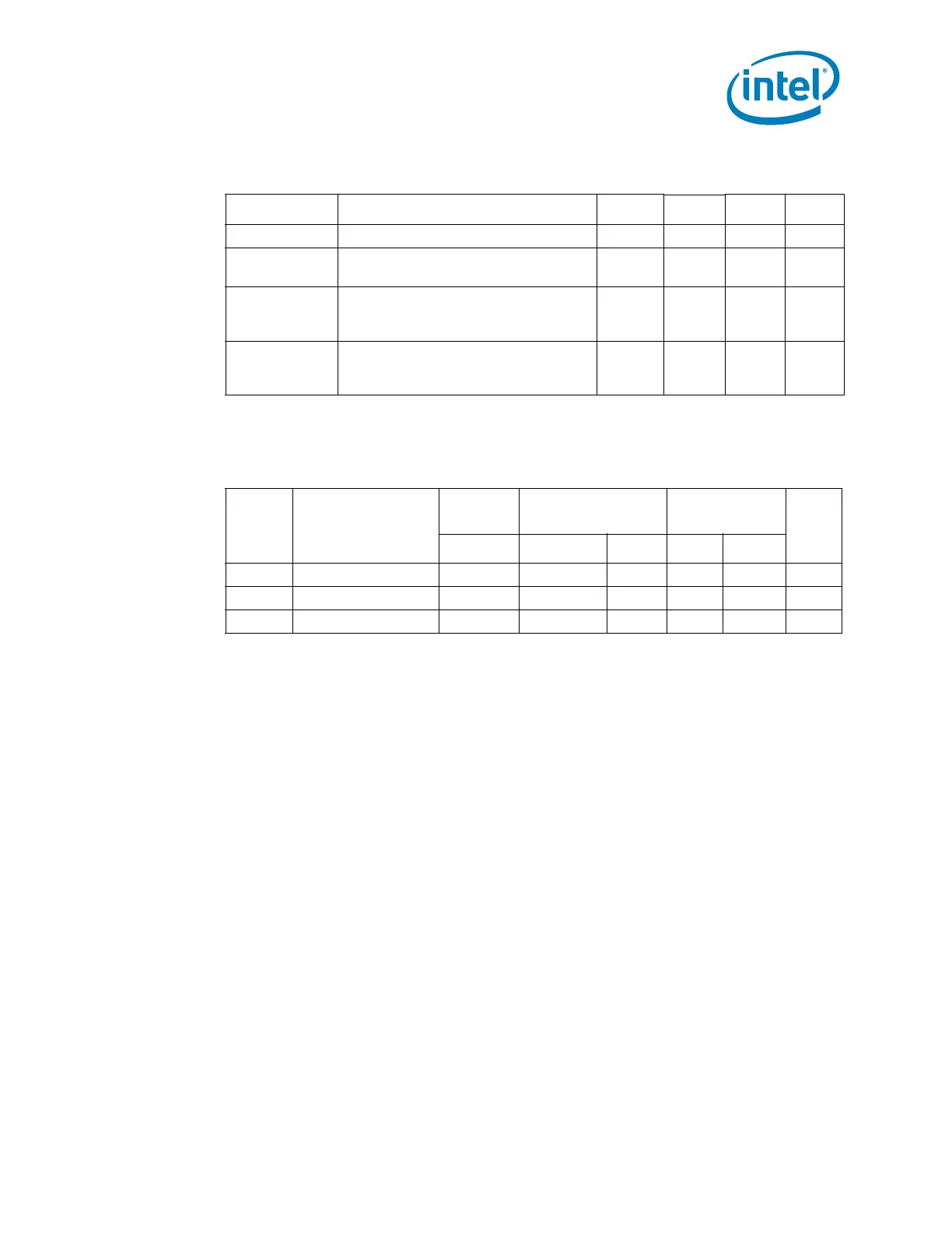
Table 8-20. DisplayPort Aux Interface
Symbol Parameter Min Nom Max Unit
UI Aux unit interval 0.4 0.5 0.6 µs
T-
Aux_bus_park
AUX CH bus park time 10 — — ns
Tcycle-to-cycle
jitter
maximum allowable UI variation within
a single transaction at the connector
pins of a transmitting device
0.04 UI —
maximum allowable UI variation within
a single transaction at the connector
pins of a receiving device
0.05 UI —
Table 8-21. DDC Characteristics
DDC Signals: CRT_DDC_CLK, CRT_DDC_DATA, L_DDC_CLK, L_DDC_DATA, SDVO_CTRLCLK, SDVO_CTRLDATA,
DDP[D:C]_CTRLCLK, DDP[D:C]_CTRLDATA
Symbol Parameter
Standard
Mode
Fast Mode 1 MHz
Units
Max Min Max Min Max
F
scl
Operating Frequency 100 — 400 — 1000 kHz
T
r
Rise Time
1
———— ns
T
f
Fall Time
1
250 20+0.1Cb
2
250 — 120 ns
 Loading...
